
Clamp, control breakthrough, stop rubbing
Three sections show a clamped plate with axial drilling, reduced feed as the point breaks through, and a shiny rubbed patch without a developed hole.
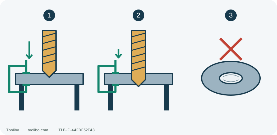
1. Axial cutting
Secure the plate against rotation; do not steer the hole by pushing sideways.
2. Breakthrough
Ease feed near the exit while maintaining control, with no hand behind it.
3. Rubbing without progress
Stop to inspect edge, material, speed and lubrication instead of forcing a dull bit.
Conceptual sections, not dimensions, chip-shape guarantees or a force scale. Support must leave a clear exit; measurements and chip removal happen only after stopping, disconnecting and safe cooling.
Identify the steel, not just a metal-drill label
The exercise makes a 6 mm through-hole in a removed, uncoated 3 mm non-alloyed construction-steel offcut without hidden objects. Its known tensile strength is 400–800 N/mm² and hardness below HRC 21. This is non-structural practice, not work on a vehicle frame, pressure vessel, live enclosure or unidentified hardened component. If the material is unknown, do not invent settings from colour, magnet attraction or sparks.
The selected bit is Milwaukee THUNDERWEB HSS-G DIN 338, 6.0 mm, article 4932352358, with 93 mm overall and 57 mm working length. The drill must permit the metal-hole diameter and shank, and provide appropriate speed control and grip. Sufficient flute length does not approve arbitrary projection or hand-held deep drilling; this example only concerns the 3 mm offcut.
HSS identifies high-speed steel, not an instruction to run as fast as possible. The manufacturer’s material matrix supports THUNDERWEB HSS-G for this steel. Harder alloy steel or stainless requires another selection: its higher-strength stainless row favours the cobalt range, not simply more oil on the existing bit. A gold appearance is not an application specification either.
Read the complete speed-table row
Milwaukee’s guidance pairs this material and the 6–10 mm hole column with 870 rpm; the coolant field permits drilling emulsion or cutting oil. This exercise uses a small amount of cutting oil compatible with steel, bit and tool requirements at the cutting point. Do not swap emulsion, oil and dry cutting while calling them identical conditions.
The 870 rpm value is a conditional starting guide, influenced by actual material, operator and tool. It is not a universal speed for all 6 mm metal holes or “half trigger” on any drill. Check a suitable mechanical range and obey variable-speed and continuous-duty restrictions; some drills prohibit prolonged operation at partial trigger. If the job requires accurately maintained speed that the hand-held tool cannot deliver, use appropriate speed-controlled equipment.
The table’s feed-per-revolution values concern controlled machining, not kilograms of hand pressure. Hand feed should sustain cutting rather than rubbing without severe speed loss, bending or loss of control.
Clamp and locate instead of pressing the work down
Keep away from smoking, leaking or dangerously hot equipment; do not handle it. Routine preparation starts only when stable and safe: release, stop and remove the battery. Wear eye protection and secure hair and loose clothing. Steel edges are sharp, but handling protection must not become snag-prone gloves used close to a rotating drill.
Support the steel steadily and use a suitable vice or clamps against rotation and lifting. Keep supports, bench and clamps outside the complete breakthrough path. Holding the plate by hand or standing on it is not secure workholding. Practise on matching offcuts rather than an installed component.
Mark the centre and, where appropriate for the material, make a small location mark with a suitable centre punch. Do not dent the sheet. Inspect for chipped edges, bending and significant wear, then secure the intact shank as the drill requires with projection appropriate to the task. This 6 mm example does not automatically add an arbitrary smaller pilot; follow a specific accessory requirement if one applies.
Complete the first hole in sequence
- With the battery still removed, confirm bit retention, ordinary drilling mode, forward rotation and a suitable speed range for the stated conditions. Check clamps, location and both hand positions.
- Apply a small amount of cutting oil at the cut according to its use and safety instructions. Keep it out of housing, battery and vents and keep grips dry. Do not reach beside a rotating bit to replenish oil.
- Insert and secure a compatible battery with your finger off the trigger. Start slowly with the tip touching the locating mark; maintain perpendicular alignment and axial feed. Do not push sideways to drag a wandering hole back to centre.
- Maintain controlled feed once cutting is established. Ease pressure near breakthrough to avoid sudden grabbing or plunging, with no hand behind the exit. Sparse chips alone are not a reason to force harder.
- After normal breakthrough, withdraw according to the drill’s normal drilling procedure, then release, stop and remove the battery. A jam is not normal withdrawal: release immediately, stop and safely disconnect before investigating, without prying or repeated trigger pulses.
- Once bit and chips are safe to handle, brush chips away with a suitable tool and inspect both openings, dimensions and burrs. Measure only stopped and disconnected. Stay isolated for deburring, bit changes or added lubrication; before more drilling, repeat assembly checks and safe battery installation.
Judge cutting, not one chip colour
Swipe or scroll horizontally to see all columns.
| Observed condition | Interpretation |
|---|---|
| Ongoing chips, steady feed and no overload | Cutting is occurring; watch breakthrough pressure. Chip form varies, so long curls are not mandatory |
| Shiny rubbing, persistent squeal and little progress | Stop and check the point, speed, lubrication and material; do not keep heating a dull edge |
| Severe speed loss, grabbed plate or bending bit | Release immediately, stop and disconnect before checking workholding, alignment and feed; do not force harder |
| Smoke, abnormal fluid evaporation or a marked smell change | Stop and isolate safely; do not continue trials while the abnormal condition remains. Resume the stated setup sequence only after the cause is corrected and safe operating conditions are restored |
Blue, short or long chips alone do not certify the setup. Check roundness, location, required size and plate distortion. If the first hole fails, correct the cause and make another offcut trial instead of repeating the faulty setup across the whole batch.