
Keep the next step out of the upper face
Two cutaway sections compare sheet contained in the target cylindrical land with excessive feed that puts the next larger transition into the top face.
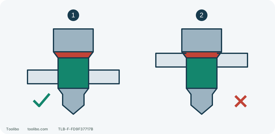
1. Target land contains the sheet
Size both faces before the next cutting edge reaches the upper face.
2. Excessive feed enlarges the top
Stop and measure disconnected; withdrawing cannot restore removed material.
Geometry schematic, not a scaled 48899320 profile. The green band is the target sizing land; the red shoulder is the next larger cutting transition. The 4 mm family limit does not replace checking actual usable land length.
Confirm that this is a thin-sheet job
This exercise uses a Milwaukee 48899320 step drill to make a 10 mm through-hole in a removed, clampable 2 mm aluminium offcut. It covers non-structural sheet, not drilling directly into an enclosure with electrical components, residual pressure, unknown coatings or hidden objects. If fitting a connector or grommet, its specification determines the hole; do not copy 10 mm simply because it is convenient.
The 48899320 covers 4–20 mm in 2 mm increments: nine sizes, an 8 mm shank and 65 mm overall length. The family specifies a maximum 4 mm material thickness and recommends suitable coolant. Being below that thickness does not establish suitability for every material. Check the actual alloy, drill’s metal-working capability, chuck range and liquid restrictions.
Select cutting lubrication compatible with the aluminium, accessory and tool. Keep liquid out of drill, battery and electrical parts. Water or household lubricants are not universal substitutes. If the requirements cannot be met together, use appropriate machining equipment instead. A drill’s maximum no-load speed is not a step-drilling speed setting.
Identify both the wanted step and the next unwanted one
Keep away from smoking, leaking or dangerously hot batteries; do not handle the equipment. Perform routine inspection only when stable and safe: release, wait for a complete stop and remove the battery.
In good light, read the markings and use suitable measuring equipment to identify the 10 mm sizing land and the next larger 12 mm step. Do not count by colour from the tip or measure beside a rotating bit.
Viewed from the side, the sheet must fit within the usable cylindrical section of the target diameter. Its underside must reach 10 mm before the 12 mm transition cuts the upper face. The manufacturer’s 4 mm maximum is a product limit, not a measurement promising 4 mm of usable land at every step. Inspect actual land length and transition geometry; resolve wear, chips or unreadable markings first.
A visible target reminder away from the cutting edge can help, but is not a physical stop. Do not wrap loose tape around the bit or use fingers as a depth limiter. Control comes from understanding the geometry, easing feed and stopping to inspect before the next step enters.
Do not hold thin sheet by hand
Support the sheet steadily and clamp against rotation and lifting. Leave room beneath the hole for the point and smaller steps to pass; backing, supports and bench must remain outside the planned travel. Holding a little sheet in pliers while drilling it in mid-air still allows it to swing if caught.
Clear the area, wear suitable eye protection and secure hair, jewellery and loose clothing. Sheet edges and chips can cut; arrange handling protection separately from rotating operation. Do not work close to the rotating bit with gloves that could be caught.
Mark the centre on the offcut, check that it is flat and uncracked, and arrange clamps so the drill can remain perpendicular. Tilting to dodge a clamp makes an oval hole; move the clamp instead.
Start small and finish at the target step
- With the battery removed, secure the undamaged 8 mm shank as the drill requires and check retention. Jaws must not bear on the stepped cutting section.
- Select ordinary rotary drilling, not hammer action. Set speed for the exact accessory and material, and check direction, lubrication arrangement, clamping and hand positions.
- Insert and secure a compatible battery with your finger off the trigger. Start slowly with the tip touching the centre mark. Maintain perpendicular alignment and steady axial feed without rocking sideways.
- Approach the target progressively and identify the 10 mm land. Ease feed near completion so it sizes the full sheet thickness without letting the 12 mm cutting edge enter the upper face.
- Release, wait for a full stop and remove the battery before examining both faces and measuring. Once cool, clear chips with a suitable brush, not fingers. If the hole is unfinished, recheck assembly and repeat safe battery installation before removing a little more material.
A spinning sheet, sudden grabbing, persistent squeal, smoke or clear distortion means stop. Release, stop and disconnect before investigating workholding, material, wear or settings. More pressure is not the response to an abnormal condition.
Recognise completion rather than another step
Swipe or scroll horizontally to see all columns.
| Result | Meaning and action |
|---|---|
| Both faces meet the fitting’s hole requirement, sound wall and flat sheet | Finish this hole and address burrs as the assembly requires |
| Large opening on top, small underneath | The target may not be through, or a larger transition may already have cut the top; measure disconnected rather than blindly feeding another step |
| Hole exceeds 10 mm | Withdrawing the bit cannot restore size; assess replacement or a solution permitted by the fitting design |
| Oval hole or lifted sheet | Check perpendicularity, support and clamping; stop repeating that setup |
Deburring does not mean drilling the entire next step into the hole. If changing to another deburring tool, disconnect first and use a suitable sheet-metal process, then recheck final dimensions. A large chamfer may remove the support a grommet or connector needs.