
Two power and mounting routes
Two panels identify the corded WX686L with disconnected cord and removable wrench, and cordless WX697L with battery isolated and Hyperlock lever, alongside exact angle and oscillation ranges.
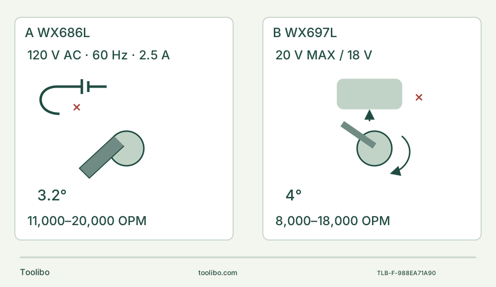
A · Qualify the complete corded route
Match the 120 V AC, 60 Hz, 2.5 A body and safe cable path. Unplug, use the removable wrench for the correct open-slot or closed-hole route, tighten, then remove and store the wrench.
B · Qualify the complete cordless route
Match the actual commissioned listed battery/charger system. Remove the battery, complete the correct Hyperlock and flange route and verify secure seating. Fixed 4-degree motion and 8,000–18,000 OPM do not establish superiority or universal accessory fit.
Original schematic. Isolation symbols mean physically disconnected supply; they do not depict exact pack removal direction or a permitted electrical adapter. A is a separate removable wrench, not Hyperlock. B summarizes a lever-operated clamp, not a complete assembly sequence: lift and unlock, seat the exact accessory, turn to clamp and fold fully home. Closed-hole accessories require the documented complete flange/shaft removal and reinstallation. Ratings are not comparative performance measurements.
Choose the mounting and power workflow together
The US Worx WX686L and WX697L share an oscillating-tool family name, but they are not the same body with different packaging. WX686L is a 120 V AC, 60 Hz, 2.5 A corded tool using a removable clip-in wrench to operate its flange fastener. WX697L is an 18 V nominal/20 V Max cordless body using a Hyperlock lever and its matched flange assembly. A familiar-looking piece on top of the head does not justify using the other tool’s mounting procedure.
This comparison uses WX686L instructions AR01339301 and WX697L instructions AR01580701, matched to the actual US tools. It chooses a complete existing-owner route for a small cut in visible loose wood. It does not compare prices, current kit contents, runtime or measured cutting performance. Suffixes describing package variations are not additional mechanical models.
First qualify what supplies the selected body
For WX686L, confirm the actual nameplate, a suitable outlet, an undamaged cord and plug, and a cable route outside the work, clamps and complete blade envelope. A reachable outlet alone is not enough if the lead would cross the cut or pull on the tool. This example assumes direct suitable supply; any extension must separately satisfy the exact electrical instructions. Damage to a cord requires qualified replacement, not a taped repair.
For WX697L, use only an already commissioned actual battery/charger system permitted by its manual and those components’ own instructions. The tool table lists battery models WA3520, WA3525, WA3575 and WA3578, and charger models WA3742, WA3875 and WA3881. These names are an identity check, not a charging lesson or permission to use any battery labeled 20 V. If the owner’s actual pairing or instructions cannot be confirmed, the cordless route is not ready merely because the pack slides in.
Before assembly, stop the tool, wait for the accessory to stop and physically isolate it: unplug WX686L or remove WX697L’s battery. For the latter, follow the actual release-button and slide-out arrangement; the schematic is not a removal-direction instruction. Switch OFF before restoring either supply. Do not treat a dark LED, a stopped motor or a retained switch setting as physical isolation.
Match the blade and its opening before touching the fastener
Select an intact, sharp wood end-cut accessory explicitly intended for the exact body and known material, with packaging or equivalent manufacturer identification available. The WX686L manual’s wood end-cut row and the WX697L standard wood end-cut row support wood; that is the bounded example here. Verify the actual blade’s usable reach, shape and mounting geometry. A nominal blade width is not an allowable stock-thickness rating.
“Universal Fit” and a list of brands do not certify every current accessory, every Starlock tier or an unidentified adapter. An open slot and a closed mounting hole require different handling even when the accessory is otherwise approved. Do not enlarge an opening, force a mismatched interface, add improvised washers or transplant the other body’s fastener. Missing exact hardware is a parts-evidence hold, not a reason to run a trial fit.
Wear protective gloves for sharp accessory changes and allow hot parts to cool. Keep fingers away from the teeth and clamping pinch points. Both procedures below remain physically isolated until the installation and adjustment-item checks are complete.
WX686L: remove the wrench, then use and store it
Pull the clip-in wrench out of its top storage position. Engage it with the flange fastener. For an approved open-slot accessory, loosen the flange enough to insert the accessory as Figure B1 shows. For a closed-hole accessory, Figure B2 instead shows removing the fastener, positioning the accessory and reinstalling the matched fastener. Do not treat a closed hole as though it can slide through a partly loosened assembly.
Make sure the accessory is correctly seated on the actual interface. Tighten the flange using the wrench as Figure C shows; no numerical torque is provided here. Lift the wrench out of the fastener and clip it back into its storage position, following Figures D and E. Leaving an adjustment wrench engaged is not a completed ready-to-start state. This is a wrench-operated mounting system, not Hyperlock and not tool-free jaws.
WX697L: unlock, clamp and fold the lever home
With the battery removed, lift the Hyperlock lever and turn it to unlock the flange before sliding in the approved open-slot blade, following Figure A. Fully engage the actual mounting interface. Turn the lever to clamp, then fold it fully home as Figure B shows. Merely putting the lever down without completing the clamping action is not the documented sequence. Do not invent a number of turns or a torque value.
For a closed-hole accessory, Figure C shows removal of the flange/shaft assembly, positioning the accessory and reinstalling the complete matched assembly. Then complete the clamping and lever-home sequence. This is not permission to substitute a WX686L fastener or omit a piece that seems inconvenient. Check that the accessory is secure; if the interface will not seat or the lever cannot finish its proper travel, remain isolated and resolve the exact parts or obtain qualified service.
Source basis: WX686L instructions, actual figures A–G on pages 8–9 and operating/application pages 10–12; WX697L actual figures A–H on pages 2–3 and operating/application pages 7–9.
Do not turn specifications into a speed prescription
WX686L lists 3.2 degrees and 11,000–20,000 oscillations per minute; WX697L lists a fixed 4 degrees and 8,000–18,000. The latter is not a two-angle selector, despite generic product FAQ language about other tools. Neither the angle nor the upper speed establishes that one will finish this cut faster or more neatly.
Both have a forward-ON/rearward-OFF slide and a variable speed dial. Their application tables place sawing in the high-frequency group and scraping in the low group. They do not supply a shared numbered-dial recipe. Select the frequency for the actual approved blade and material, respecting any accessory limit, and prove the setup on secured scrap. Do not use the other tool’s remembered dial position as a setting conversion. Make setting changes with the tool stopped and isolated for this comparison’s workflow.
Two practical selection cases
An owner working beside a suitable outlet already has a sound WX686L, its proper wrench/fastener and an identified compatible wood blade. The job can keep the cable clear. That complete corded route is a candidate; there is no need to buy the cordless model merely because its lever looks more convenient. Losing the wrench or finding damaged mounting parts changes that answer to “obtain the exact replacement or service evidence first.”
Another owner has a fully documented, commissioned WX697L power system and its intact Hyperlock assembly, but no safe direct cable route for the proposed bench arrangement. The cordless route may solve that cable constraint, provided its actual blade and workholding also qualify. It does not remove clamping, dust or underside-clearance requirements. If the battery/charger evidence is missing, reconsider the bench arrangement or another method rather than improvise electrical or battery adapters.
Complete and accept the chosen loose-stock cut
Use new uncoated wood of known condition, with both faces and the entire intended cut visible and free of metal or other hidden contents. Mark a modest open-edge cut only after checking actual blade reach. Clamp the retained piece to a stable support and independently control the waste so it cannot fall, close the cut or require a hand beside the blade. Keep the bench and clamps clear of the full motion and breakthrough path. This is not an installed doorframe, floor or concealed-service task.
Use eye and hearing protection, appropriate respiratory protection and dust controls for the material. Hold the tool securely with both hands on suitable grip areas, keep vents clear and stand clear of the blade path. Complete the appropriate isolated mounting sequence, remove adjustment items, confirm OFF and restore the qualified supply. Start before contacting the work, then guide with light pressure and controlled motion. The manuals describe a slight pendulum motion for chip removal; this is not permission to bend the blade, twist it sideways or lever the last uncut fibers.
At the end of normal cutting, cease contact with the work, switch OFF and wait for complete stop before setting the tool down. Unplug or remove the battery before clearing waste, turning stock, remounting a blade or inspecting a doubtful clamp. If the tool binds, the stock shifts, cutting deteriorates or abnormal heat, smell or noise occurs, stop and isolate before investigation. Do not apply the manuals’ ordinary low-speed no-load cooling advice as a blanket recovery for an unexplained fault. There are no user-serviceable internal parts in this workflow.
Inspect the completed cut while isolated. Accept only a fully separated result that follows the intended line and size without uncontrolled tear-out, scorching or support movement. A failed sample requires setup correction or advice before repeating; no structural tolerance or performance ranking is inferred. WX697L’s flashing low-charge LED directs attention to the documented power system, not an all-purpose fault diagnosis or a reason to force the cut.
Record the selected body, its exact mounting route, blade identity, supply prerequisite and successful sample setup. The final decision is “this complete system is suitable for this known job,” “obtain the missing exact evidence or part,” or “stop for qualified service.” It is not “all Worx blades and top levers work the same.”
Models referenced