
Match mains, secure the flange and route the cord
Three panels show WX686L 120 V AC 60 Hz 2.5 A identity, a separate wrench and flange assembly with disconnection reminder, and clamped wood with the cord routed away from the cut.
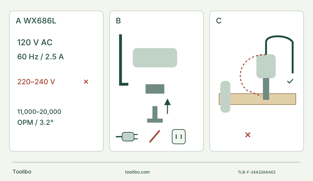
A · Match the US supply
Confirm actual 120 V AC, 60 Hz and 2.5 A nameplate. Do not connect directly to 220–240 V. Overall speed is 11,000–20,000 OPM, not a numbered dial map.
B · Use and remove the wrench
Unplug, remove the stored wrench, loosen the flange and use the correct open-slot or closed-hole route. Tighten, lift the wrench free and clip it back into storage.
C · Keep the cord clear
Secure the sample, support the cut and route the cord behind the tool away from blade and waste. Start clear of the work and stop fully before setting down.
Original schematic freshly checked against actual manual figures A–G. B is not a tool-free lever or a precise holder drawing; its plug symbol means disconnect before adjustment. C marks an unsafe cord route, not the blade oscillation envelope, and does not replace complete support planning.
Identify the corded body, not just a kit title
This guide takes an existing US WORX WX686L from inspection through a short, supported wood cut and safe storage. It is based on the exact WX686L manual, AR01339301, copyright 2018, linked in the manufacturer’s current WX686L.1 kit page. The kit suffix does not create a second mechanical model, and a current sales page does not mean every pictured accessory is in an owner’s box. Match the actual tool, original mounting parts and supplied instructions before proceeding.
The essential difference is the removable clip-in wrench. It is stored on top of the tool but must be taken out and used to loosen and tighten the flange. This is not a Hyperlock lever, a snap-in jaw system or a tool-free accessory change. If the wrench or correct fastener is missing, complete the proper system before cutting; do not substitute a random screw or force an accessory onto the holder.
The finished outcome here is a controlled short cut in loose, known, unfinished softwood. Both faces must be visible. Installed flooring, wall openings, old painted trim, chemically treated wood and hidden services are outside this first project. A blade’s material list does not identify what is inside an unknown assembly.
Match supply and keep the cable out of the work
The matched US machine is 120 V AC, 60 Hz, 2.5 A, with Class II double insulation. Confirm that the physical nameplate agrees and use an appropriate matching supply and outlet. Do not connect this body directly to a 220–240 V circuit, modify the plug or improvise an adapter. The insulation class does not make a damaged cable safe or permit cutting a live wire.
Inspect the plug, entire accessible cable, switch, housing, holder and accessory before use. A cable cut, loose part, damaged mount or switch that cannot reliably turn the tool on and off is a service stop. Keep the tool dry; this bench project is not a damp-location task. The general manual requires an RCD-protected supply if damp operation is unavoidable and an outdoor-rated extension when working outside. It does not supply a numbered extension-gauge table for this article to invent. If an extension is necessary, qualify its rating and condition separately before proceeding.
Route the cord behind and away from the blade, its full travel and the waste area. Give it enough freedom for the whole cut without letting it cross the work or pull the tool sideways. Check that clamps, bench edges and your feet will not trap it. Hold insulated gripping surfaces, but treat that precaution as a last protective measure, not permission to work where an energized conductor may be cut.
Slide the switch backward OFF and remove the plug before mounting, adjusting, checking or cleaning. Keep the disconnected plug under your control. OFF is not electrical isolation. Confirm OFF again before reconnecting; do the same after an interrupted supply rather than assuming an unclaimed electronic restart-prevention feature.
Select the actual wood accessory and its mounting route
Use an appropriate accessory expressly intended for this tool, following its packaging and mounting instructions. The manual identifies a standard wood end-cut blade and shows a wood end-cut application. For this project, use the actual compatible, identified wood blade with sharp, undamaged teeth. Keep its usable cutting reach appropriate to the sample thickness and leave clearance for the complete motion below and beyond the cut.
The holder is called Universal Fit, and the old manual lists other brands. Neither is proof that every present accessory sold under those names, or every Starlock, Plus or Max product, will fit. Verify the exact interface rather than buying on brand alone. Do not file a mounting hole, stack improvised spacers or install an unverified adapter. An accessory that cannot seat correctly with the specified parts is not ready for operation.
With the tool unplugged and cool enough to handle, wear protective gloves for sharp or hot accessories and keep fingers away from the teeth:
- Pull the clip-in wrench out of its storage position on top of the machine. It is a removable tool, not a captive clamping lever.
- Engage the wrench in the mounting mechanism and loosen the flange in the direction shown by the unlock symbol in the manual.
- For the illustrated open-slot accessory, loosen enough to insert and seat it under the flange. For a closed-hole accessory, remove the fastener, place the accessory on the holder and reinstall the fastener. These are different routes; do not force a closed hole sideways under an attached fastener.
- Fully seat the matching interface and tighten the flange with the wrench as shown by the lock symbol. The manual gives no numerical torque here, so do not invent one. Do not rely on finger-tight contact or storage of the wrench to finish the clamp.
- Lift the wrench out of the adjustment position, then clip it back into its designated storage location. Check secure accessory seating while still unplugged and ensure no adjusting tool remains engaged.
If the accessory rocks, cannot sit correctly or cannot be retained securely, stop and resolve the actual parts or holder problem. Do not energize it to see whether vibration will settle it. Subsequent reorientation or replacement repeats the unplugged procedure. Allow a used blade to cool before touching it; a stopped blade may still burn or cut.
Build a supported cut before plugging in
Clamp and support the wood on a stable platform. Never hold it in a free hand or against your body. Mark the short cut clearly and inspect its entire route, thickness and underside for foreign objects. Position supports so they do not close the kerf or force the blade against the bench. Control the waste without placing a hand in the blade path. A small sample that cannot be secured with enough clearance is the wrong sample for this setup.
Provide good lighting, a stable stance and an uncluttered work area with bystanders clear. Wear eye and hearing protection and appropriate dust protection. Wood dust still requires attention even without paint: work with ventilation and use suitable dust collection where provided and connectable. The accessory list’s reference to a perforated sanding pad does not establish a complete saw-blade extraction system. Unknown coatings and hazardous dust sources require another assessment, not just a different mask.
Keep handles dry and clean, clothing and hair clear, and hands above and away from the cutting envelope. Plan how to reach the switch without losing control. The schematic shows the cord route and a clamp, not a complete support prescription; inspect your own bench arrangement.
Choose the frequency without inventing a dial recipe
The tool’s overall no-load range is 11,000–20,000 oscillations per minute, with a stated oscillation angle of 3.2°. The manual’s working table puts sawing in the high-frequency group. It does not provide a numbered dial-to-frequency map or a model-specific numerical initial-plunge setting. Do not borrow a level-3 rule from another brand or treat the range endpoints as a calibration of every dial mark.
Choose a setting consistent with the actual accessory and material instructions, and make a controlled trial on the secured scrap. Make setup adjustments with power disconnected. Maintain a sharp blade and avoid prolonged operation at very low speed. More pressure is not a substitute for the correct frequency or a serviceable accessory.
Start clear, feed lightly and finish under control
With the flange secure, wrench stored, switch OFF and cord route checked, connect the qualified supply. Hold the tool firmly at its insulated grips, keeping hands away from the head and underside of the work. Slide forward to turn ON while the accessory is clear of the material. Begin cutting only once the tool is running under control.
Feed with light pressure and steady movement. The manual permits a slight pendulum motion during plunge and sawing work to help chips escape. That is not permission to twist the blade sideways, lever the kerf apart or sweep the tool into a clamp. Keep the intended path and full clearance controlled. Excessive force increases load and accessory wear rather than providing a reliable faster cut.
If the material shifts, the cord approaches the blade, the accessory binds or the tool behaves abnormally, move OFF, wait for the accessory to stop and unplug before correcting the cause. Do not reach under a running blade or pull a cable through the cut. If power is interrupted, set OFF and inspect the situation before reconnecting.
Finish the last part without letting waste tear away or pinch the blade. End contact with the work before moving the switch rearward OFF, then wait for complete stop before putting the machine down. Unplug before inspecting the cut or clearing chips near the accessory. A finished edge may be sharp or splintered; inspect without running fingers along it.
Separate ordinary cooling from a fault
The manufacturer suggests running at maximum speed without load for two to three minutes if ordinary low-speed use has made the motor too hot. This is a limited cooling instruction, not permission to continue cutting a hot tool, restart a jammed accessory or override a protective shutdown. First stop and assess the situation. Only an otherwise intact, freely running tool in a controlled, clear position belongs in that no-load cooling scenario.
Smoke, a burning smell, damaged insulation, abnormal noise or repeated loss of operation requires unplugging and qualified service. The manual notes that occasional internal sparks may be visible through the vents; do not use that note to dismiss signs of damage. There is no basis here for a guaranteed thermal-reset sequence or electronic restart protection.
Leave the complete system ready for storage
With the plug removed, wipe the tool with a dry cloth. Use no water or chemical cleaners, keep ventilation slots and controls free of dust, and do not add lubrication or open the motor. The manual identifies no user-serviceable internal parts. A damaged supply cable must be replaced by the manufacturer, service agent or similarly qualified person; repairs use identical replacement parts.
Check that the correct wrench and mounting parts remain with the tool. If removing the blade for storage, repeat the isolated wrench/flange procedure and protect its sharp edges. Store the machine dry and inaccessible to children without stressing the cord.
Sanding is a separate setup: its pad is installed with the fastener route shown in the manual, and a suitable sheet must be fitted before starting. Do not wear the sheet through to the pad; use appropriate grit, light pressure and a scrap trial. That brief boundary does not approve sanding old coatings or supply missing dust equipment. Complete the wood-cut project first, with the tool stopped, unplugged, clean and inspected.
Models referenced