
Four inventory gates before choosing a tool
Four panels show identified and unknown accessory cards, MM35 documented rating and final clockwise knob, native BD200MT lever versus a questioned H/I/J/E adapter inventory, and a complete-system checklist before a supported wood cut.
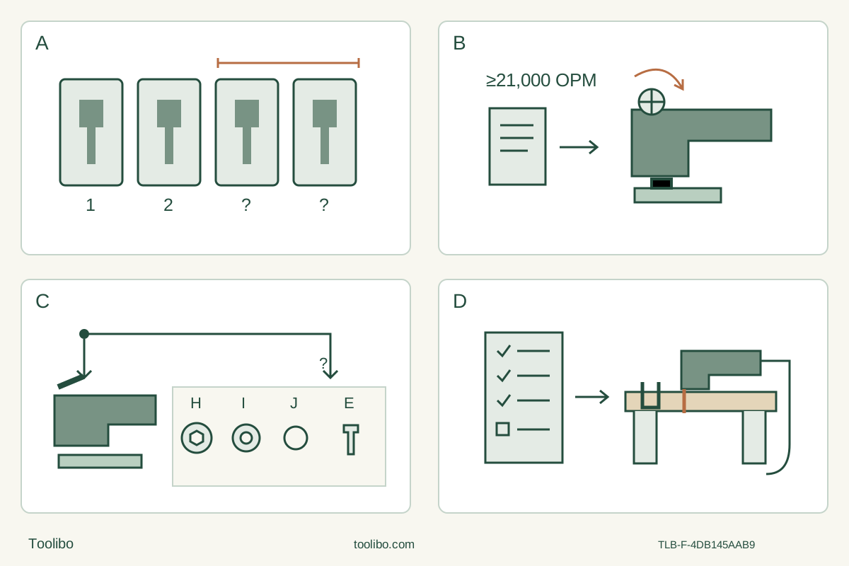
A · Separate identified stock from unknowns
Record exact blade identity, material and rating. Similar holes or a larger box of blades do not prove a usable system.
B · Complete the MM35 route
Use the matched Dremel accessory and required rating; loosen, press, seat all actual pins flush, release temporary spring retention and finish full clockwise hand-tightening.
C · Do not merge the BD200MT branches
The Type 2 native route uses its lever. H/I/J/E belong to a separate documented adapter branch; unidentified parts or compatibility mean hold, and the adapter is prohibited with native accessories.
D · Choose only a whole supported job
Confirm supply, controls, actual blade reach, clamping and dust precautions before the loose-stock sample. Stop and isolate for correction, then accept or reject the completed cut against the intended result.
Original schematic, not installation dimensions or an actual pin count. B applies the at-least-21,000-OPM rule only to the matched MM35 Dremel accessory route; releasing its temporary spring hold still requires full clockwise hand-tightening. C separates native BD200MT use from an unresolved adapter parts inventory, not a stacking order: never use that adapter with native BLACK+DECKER accessories. D requires two-hand operation, full cutting clearance and controlled waste support as described in the body.
Count documented working routes, not blades in a box
An owner has two corded oscillating tools and a mixed accessory drawer. The useful question is not which machine accepts the largest-looking pile. It is which complete, documented combination can do the next visible loose-stock job without an unknown interface, incomplete clamp or unsuitable supply. This comparison ends with a selection, a parts-evidence hold or a service handoff—not a powered fit experiment.
The Dremel route is the US MM35 matched to its August 2018 instructions, 1600A014GW. The BLACK+DECKER route is a physical BD200MT Type 2 matched to June 2014 instructions 90613711. The generic BD200MT FAQ links a different 2011 document; do not combine its ratings or assembly details with this Type 2 route. These are document-matched owner systems, not assertions about the contents or revision of a current retail kit.
Make two separate inventory sheets
Switch each tool OFF, unplug it, wait for all motion to stop and allow hot accessories to cool before handling. Wear protective gloves for sharp accessory changes. Photograph or write down the body identity, electrical nameplate, actual manual identifier, accessory marking and the parts that belong to that holder. Keep unknown blades and loose hardware in a separate unapproved group. A logo, similar mounting hole or apparently snug fit is not compatibility evidence.
For MM35, the assembly rule is Dremel accessories rated at least 21,000 OPM. Record both identity and rating; do not qualify a different maker’s blade merely because its printed speed is high enough. The matched material table identifies MM480 for softwood, with an 8–10 speed recommendation. Its other rows do not authorize every material on every blade.
For Type 2 BD200MT, the native BDA1214 wood plunge blade is a documented route for the clean wood example below. Its accessory table also names PVC/plastic and drywall, but that does not transfer those materials to the MM480 or make every blade in the drawer equivalent. Marking, permitted material, sharpness and the usable cutting reach must all be suitable for the actual task.
Source basis: MM35 instructions, pages 8–9 and 13; BD200MT Type 2 instructions, pages 6–7 and accessory table page 13. The BLACK+DECKER FAQ is evidence of a document difference only, not operating authority here.
The clamps impose different completion checks
On an unplugged MM35, turn the clamping knob counterclockwise to loosen it, then press it so the flange extends enough for the accessory. Seat the accessory on every actual locating pin, flush against the holder. Release knob pressure: the spring holds the blade temporarily while it is secured. Finish by turning the knob clockwise and tightening fully by hand until it cannot be turned further without becoming uncomfortable. Temporary spring retention is not the final clamp. Do not add pliers, a guessed torque or another model’s audible-click requirement.
On an unplugged BD200MT Type 2 using its native accessory, squeeze the clamping lever. Check that the shaft and holder are clean, slide the accessory between them with its working edge facing away from the tool, and seat it flush on all actual pins. Release the lever and verify secure engagement. Neither the diagram here nor a remembered pin count substitutes for inspecting the actual intact holder.
The Type 2 adapter is a separate branch, not an upgrade to the native clamp. Its instructions explicitly prohibit using the adapter with BLACK+DECKER accessories. The illustrated separate route involves adapter plate H, pressboard I, O-ring J and bolt E; the plate’s protrusions face upward in that documented assembly. Finding four roughly similar loose parts does not establish that they are the right parts or that an unidentified third-party accessory is approved. Obtain the exact parts and compatibility evidence and follow that complete branch before considering such a system usable. This comparison does not authorize assembling a mixed stack from the drawer.
If a native accessory will not sit fully flush, a part is damaged, the lever will not close correctly or the MM35 knob cannot complete its documented tightening, stop. Correct only an obvious documented installation omission with the power disconnected. Persistent uncertainty or damaged holder parts requires qualified service—not an energized wobble test, an extra washer or a hardware-store bolt.
Supply and controls are part of the inventory
MM35’s matched manual specifies 120 V AC, 60 Hz. For Type 2 BD200MT, qualify the actual electrical nameplate and its supplied instructions; do not borrow an amperage from the earlier FAQ attachment or another type. A sound cord and plug, correctly matched supply and a safe cable route are required. This decision assumes a suitable direct outlet. If an extension is necessary, its gauge, length and rating must be separately checked against that exact tool’s instructions; the other tool’s table is not a substitute. Damaged leads are a service hold, not a taping exercise.
Both examples use a slide switch pushed forward for ON and back for OFF. Check OFF before reconnecting. Their dials are not interchangeable: MM35 has a ten-position scale, whereas Type 2 BD200MT has positions 1–6 and retains the selected setting. A written note saying simply “wood at 4” is therefore not a transferable instruction.
For the MM480 clean-softwood route, MM35’s table says 8–10, while its cutting instructions separately call for medium speed for the initial plunge to improve control, then permit increasing speed. Do not reinterpret the table as a maximum-speed entry command or invent a numbered medium setting. Type 2 BD200MT recommends 4–6 for wood and says to start low and increase when unsure; do not silently transplant the Dremel entry wording or assume equal OPM at equal numbers.
Worked choice: a small open-edge notch in known loose softwood
Suppose the intended result is an open-edge notch in a new, uncoated softwood sample. There are no prescribed dimensions here: mark a modest test shape only after checking the chosen blade’s actual usable reach and the complete motion envelope. Inspect both faces and the entire cutting region for metal, coatings and other uncertainty. This is not an installed trim, wall or hidden-service cut.
If the owner has a positively identified MM480, its required rating, the matched MM35 and a sound complete supply, that is one candidate route. If the owner instead has the native BDA1214 and the matched Type 2 body, that is another. If both are complete, select the one whose actual blade geometry, access and documented controls suit the proposed sample. The manuals do not establish a winner for cut quality, power or speed; no comparative performance test is claimed.
Lay out the cuts and clamp the retained stock securely. Support the waste so it cannot drop, pinch the blade or be held by a hand near the cut. Keep clamps, bench and cable outside the full blade path, including breakthrough below and beyond the marked line. If the final cut cannot leave both sides safely controlled, change the workholding or choose another method rather than improvise during cutting. Use the actual instructions’ eye, hearing and suitable respiratory protection and appropriate dust controls; a sanding attachment is not automatically saw-blade extraction.
Complete the selected isolated installation above, remove adjustment items and check the intended switch/dial state. Keep both hands on the tool, wear the required protective gloves during MM35 use, keep body parts clear and vents unobstructed. Start with the blade clear of the work, then enter using that tool’s documented speed approach and light pressure. Do not bend or twist the blade to meet a line, force the last bridge or exceed its usable reach. Stop for unexpected movement, burning, poor progress or a changed clamp condition. Switch OFF, wait for full stop and unplug before investigating, turning the sample or changing the accessory. Never restart a blade trapped in the cut.
After the last cut, switch OFF, wait for complete stop and unplug before removing the waste or checking the result. Accept the sample only if the notch follows the intended lines and size, has fully separated, and shows no uncontrolled tear-out, scorching or evidence of shifted support. Remove loose splinters safely with the tool isolated. A failed sample means revise the setup or seek advice before another cut; it is not proof that the other brand is better. No structural-fit tolerance is supplied here.
Record the actual selection
Keep the selected body/manual, blade identity and rating, complete mounting parts, supply qualification and task-specific setup together as one usable route. Record unknown accessories as unknown, not as savings. A documented compatible part that is missing may justify obtaining the exact replacement; a damaged holder calls for a service quote; an undocumented adapter stack remains on hold. Do not buy a second body solely to rescue an unidentified box of consumables. The useful inventory is the number of supported complete jobs—not the number of pieces that can be pushed onto a holder.
Models referenced