
Supply, extension, isolation and qualified service
Four panels show MM35 120 V AC 60 Hz and 3.5 A, the 3–6 A extension-cord table, a disconnected plug and neutral flange symbol, and Dremel brush service at 50–60 hours.
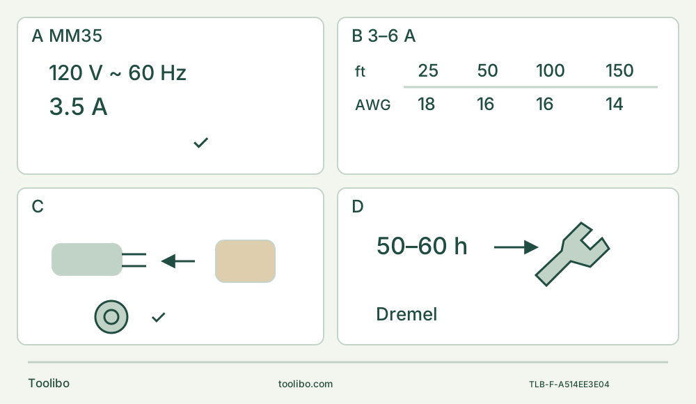
A · Match the documented supply
Confirm the actual US MM35 nameplate: 120 V AC, 60 Hz, with the same-period 3.5 A model identity. Do not substitute DC or another regional body.
B · Use the matching extension row
For the documented 3–6 A row, 25/50/100/150 ft correspond to 18/16/16/14 AWG; actual cord condition, location and current still matter.
C · Unplug before the complete clamp
Loosen counter-clockwise, press, seat all pins flush, release the temporary spring hold, then fully hand-tighten clockwise. The flange icon is uncounted schematic geometry.
D · Leave internal work to service
The 2018 manual recommends brush service at 50–60 operating hours by a Dremel service facility. Unplug before care; faults require attention without waiting for the interval.
Recovered original figure was freshly checked and its counted locator dots replaced by a neutral flange symbol. It specifies no pin count. The wrench means service-facility work, not owner disassembly.
The spring holds the blade only while you finish tightening
The MM35’s Easy-Lock knob performs two different jobs. Pressing the loosened knob extends the clamping flange so an accessory can be inserted. Releasing it lets the spring hold the blade temporarily. The final clamp is made by turning the knob clockwise until fully hand-tightened as the manual directs. A blade that stays in place under spring pressure is not ready to run.
This is an existing-owner guide for the US MM35 Multi-Max matching Dremel document 1600A014GW MM35 08-18, dated 23 August 2018. That manufacturer-hosted file contains the complete English instructions even though its storage URL includes es-us. The same-period official launch identifies the 3.5 A model. Neither source establishes the latest supplied revision, current stock or present kit contents. If the actual nameplate, knob-and-flange holder or owner instructions differ, resolve the match before following this procedure.
The complete outcome is a secure MM480 wood blade and a short cut in a known untreated softwood offcut, with both faces accessible, followed by inspection and isolated storage. This is not a guide to opening walls, cutting hidden services, removing unknown paint or restoring glazing. The source contains those broader application examples, but they require qualifications beyond this sample.
Check the supply and cord before the accessory
The matched tool is rated 120 V AC, 60 Hz. Confirm its actual nameplate and a suitable supply; do not run an AC-only tool from DC or modify the plug to make it fit. Inspect the cord, plug, housing and switch for damage. A switch that cannot reliably start and stop the tool, or damaged wiring, requires service rather than a trial cut. Only a Dremel service facility should service the power cord.
Keep the switch backward at OFF and the plug disconnected during setup. Route the cord behind the tool and clear of the blade, workpiece edges and hot surfaces, without creating a trip or pull hazard. Do not carry or unplug the tool by pulling the cord. Work dry; this tool is not for wet sanding or working over liquid-soaked material.
Avoid an unnecessary extension. If one is required, use an intact, correctly rated cord for the location and the actual nameplate current. For the documented 3.5 A tool, the manual’s 3–6 A, 120 V row specifies 18 AWG at 25 ft, 16 AWG at 50 ft, 16 AWG at 100 ft and 14 AWG at 150 ft. These are the matched table’s length-and-gauge pairs, not interchangeable numbers or permission to combine cords arbitrarily. A smaller AWG number means a heavier conductor. Outdoor work requires an outdoor-suitable extension; unavoidable damp-location operation requires a GFCI-protected supply, not wet use of the tool.
If starting or running is abnormal, switch OFF, unplug and investigate the supply or service condition. Do not treat a higher dial setting as a general repair for voltage drop, damaged connections or an unsuitable extension.
Qualify the exact blade and the material together
The 2018 manual requires Dremel accessories rated at least 21,000 opm. For this sample, use an actual identified MM480 HCS wood flush-cut blade in sound condition, with a matching holder and enough usable cutting reach for the planned short cut. The table identifies that exact blade; it does not establish that a later similarly named accessory or an added suffix is mechanically equivalent.
Check for cracks, missing teeth, bending and contamination before each use. Do not use an accessory whose condition is doubtful, even at low speed. Confirm the wood is genuinely untreated, free of fasteners and suitable for the blade. The MM480’s wood entry is not permission to cut embedded nails, steel or unknown composite material. If the correct blade or its identity is missing, pause the cut rather than borrowing a universal-fit claim from another model.
Unplug, loosen, press, seat, release and tighten
Let a previously used blade cool before handling it, and wear protective gloves for sharp edges. With the plug disconnected, turn the clamping knob counter-clockwise to loosen it. Press the knob so the flange extends far enough to fit the accessory between flange and holder. If there is insufficient room, loosen the knob further; do not force the blade past the locating features.
Place the accessory so it engages all the interface pins and sits flush against the holder. A straight or permitted angled orientation still has to meet both conditions. Choose the angle for comfortable two-hand control, clearance from the clamp and the full intended cutting path—not merely because one pin catches.
Release pressure on the knob. The spring now holds the accessory while you finish the clamp. Turn the knob clockwise fully, until it cannot be turned further without uncomfortable effort, as the manual specifies. Do not add a wrench or invent a torque value. Check the secure, flush installation while still unplugged. If the holder or knob will not retain the accessory correctly, stop and seek the right part or service; do not test a loose mount under power.
For removal, stop, wait for all motion to end, unplug and let the blade cool. Loosen counter-clockwise, press the knob and lift the accessory off the pins, loosening further if needed for clearance. This is not a spring-eject holder and not a rotary-tool collet. Keep the same isolation rule when only changing blade angle.
Make the sample support do its job
Clamp the wood to a stable platform, with both faces and the blade’s full below-surface path visible and clear. Support the waste so it cannot drop onto a hand or close the cut. Keep clamps outside the accessory’s moving area. Mark a short cut that allows a balanced stance and does not require a hand beneath the material.
Wear eye and hearing protection, protective gloves and suitable respiratory protection; work with ventilation and appropriate dust control. Keep other people away, and exclude unknown coatings, treated wood and masonry from this exercise. Oscillation does not eliminate airborne dust. This manual does not establish an exact extraction hood or hose installation for the selected blade, so none is invented here.
Hold the insulated gripping surfaces firmly with both hands and keep the accessory working away from your body. Leave the vents uncovered. Thick cushioned gloves and regular rest periods help address the vibration exposure identified in the manual, but do not justify prolonged forced cutting. The source’s generic large-panel handling examples do not replace the clamped sample and two-hand tool control used here.
Read the speed table without turning a dial number into opm
The separate slide switch starts the tool forward and stops it backward. The ten-position dial remains a speed control, not an OFF switch. The documented approximate ranges are: setting 2, 10,000–11,000 opm; 4, 11,000–13,000; 6, 13,000–16,000; 8, 16,000–19,000; and 10, 19,000–21,000. Setting 8 does not mean 8,000 opm.
The MM480 material table gives 8–10 for softwood, 6–10 for hardwood and 2–6 for laminates. Our sample uses only the softwood entry. Separately, the cutting instructions call for medium speed at initial plunge for control, with speed increased after the initial cut. Do not read the softwood table as a command to make the first contact at maximum speed, or invent an exact numbered interpretation of “medium.” Practice on scrap and respect the actual accessory’s requirements.
The contemporary launch describes soft start and electronic feedback. Those features do not clamp a blade, detect a hidden object or provide an automatic safe-stop promise. The operator still chooses the speed, controls contact and stops deliberately.
Complete the cut with light, repeated passes
Check the switch is backward at OFF before plugging into the qualified supply. With the blade clear and a secure two-hand grip, slide forward to ON and allow the selected running speed to establish before entry. Guide the blade lightly to the marked starting point. Use a series of smooth passes, removing a little material at a time rather than forcing the whole depth in one push.
Do not twist the tool in the cut: that can bind the blade. Strong vibration during entry indicates excessive pressure in the manual’s example; ease out and correct the cause rather than pressing harder. Stop for any unusual sound, moving sample, loose attachment, burning or other abnormal behaviour. Move backward to OFF, wait for standstill and unplug before inspecting the blade, support, cord or mounting. Do not clear chips near moving teeth or reach underneath to feel the cut.
Once the intended cut is complete, stop and isolate before inspecting the cooled blade and work. Accept the result only if the line and retained material meet the intended need, support stayed secure and there is no unexplained blade movement or damage. If the result is poor, improve the support, blade choice or technique on another sample. More force is not the default correction.
Keep a later sanding setup separate
A completed wood cut does not mean a sanding configuration is ready. A later dry-sanding job needs the recommended backing pad, correctly sized hook-and-loop paper and its own material check. Install the pad with the same complete unplugged clamp sequence. Apply and align the sheet by hand; oversized paper can snag, tear or injure. The manual’s brief adhesion-running step belongs only after full assembly and safe power connection, with the pad against a flat surface—not while fitting the paper or holding it by hand.
During sanding, clamp the work, keep the pad broadly flat and move smoothly with light pressure. Do not concentrate all pressure on the point. Unplug before rotating or changing the pad or sheet; replace a pad that no longer grips firmly. Wet sanding, unknown coating removal and a borrowed control-foot procedure are not included. The VC490 paragraph mentions a control foot absent from this tool’s overview; it is not added to the MM35 owner workflow.
Finish with maintenance, not internal repair
Unplug before cleaning, adjustment or storage. Keep vents and switch areas clear without pushing pointed objects into openings or using solvents that damage plastic. If using the manual’s compressed-dry-air cleaning method, wear safety goggles and control the dust; blowing debris around an occupied work area is not a substitute for cleanup.
There are no user-serviceable internal parts. The manual recommends Dremel service-facility attention to the carbon brushes every 50–60 operating hours. That is a service interval, not permission to open the motor or an interval to ignore a developing fault. Protect the blade, store the disconnected tool securely and retain the matching 2018 instructions. The successful owner routine ends where it began: no power at the holder, correct parts, and an understanding that spring retention must always be followed by the final hand-tightened clamp.
Models referenced