
Four checks for the dated Type 2 system
Four panels show BD200MT Type 2 document identity and disconnected cord, squeeze-lever direct mounting with uncounted holder engagement, separate adapter parts, and the independent six-position dial and forward ON/backward OFF slide.
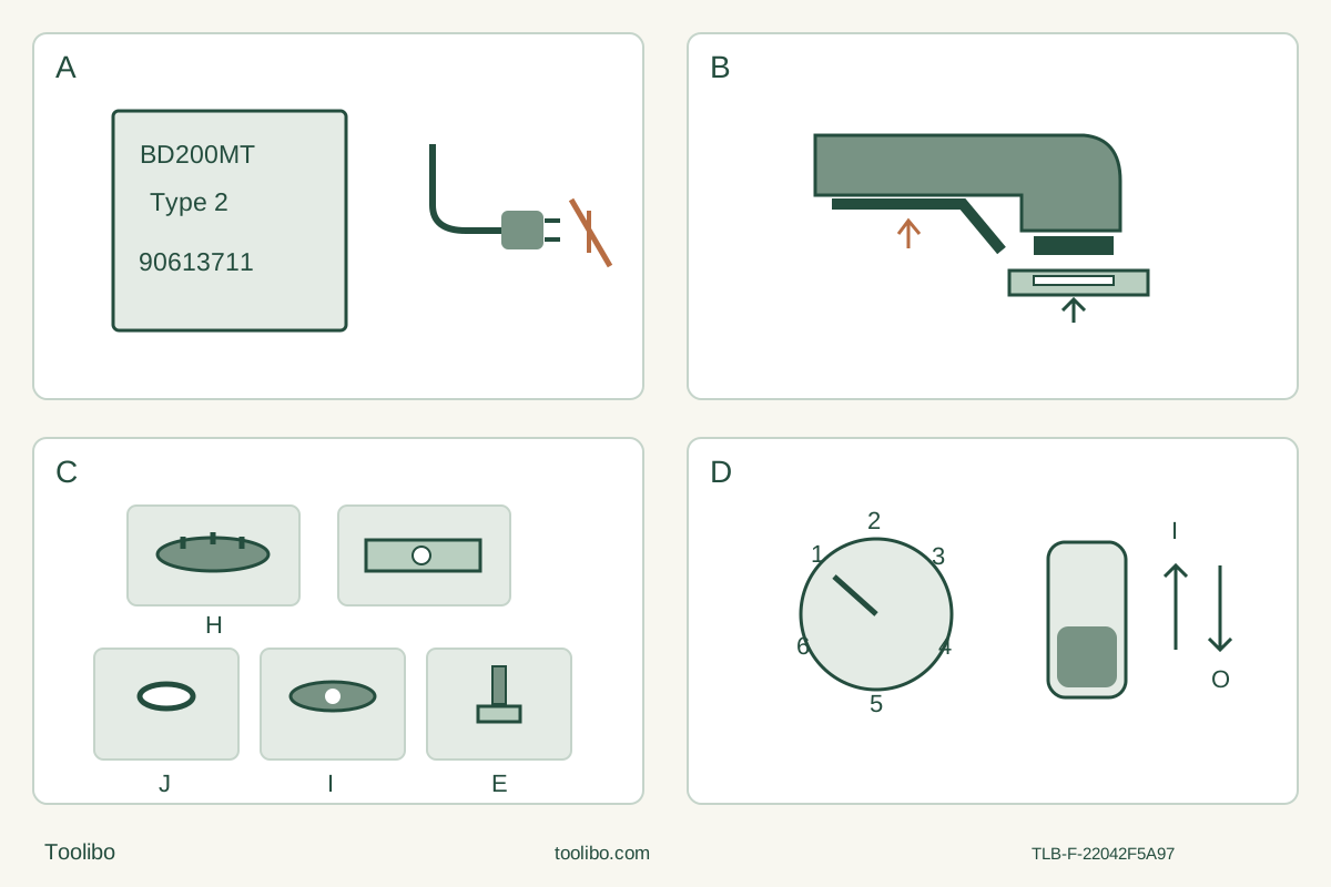
A · Match Type 2 and unplug
Confirm the actual Type 2 marking and June 2014 90613711 instructions. Switch fully OFF, wait for a stop and unplug before setup; do not import the earlier FAQ document’s ratings.
B · Seat the native blade directly
Squeeze the lever, clear debris, orient the working edge away, slide the blade between shaft and holder, engage the actual pins and seat flush. Release and check secure retention without an adapter.
C · Keep the adapter route separate
The adapter inventory is not required for native BLACK+DECKER accessories; the manual expressly forbids using the adapter with them. A different accessory needs its own complete verified route.
D · Check both speed and switch
Set and check the independent dial before power connection. Forward is ON, backward OFF; use both hands, start clear at the chosen speed and stop/unplug for sample acceptance.
Original schematic, not a counted pin pattern or assembly scale. B shows the direct native route; the working edge must face away from the housing and the actual accessory must engage fully and sit flush. C is only a separate inventory: H adapter plate, J O-ring, I press board and E bolt, plus an accessory. It is not an assembly order and is prohibited with this native blade. D shows forward toward the tool head as ON and backward as OFF; the dial retains its setting.
Identify the Type 2 tool before choosing a blade
This project ends with an inspected cut in a clamped, visible piece of untreated softwood. It is for an existing US BD200MT whose physical Type 2 marking, controls and supplied instructions match form 90613711, June 2014. The official service document is filed under BD200MTB, Type 2; its cover identifies the tool as BD200MT. That filing is not evidence of what a present-day kit contains.
Check the type marking as well as the model. BLACK+DECKER’s support instructions specifically require both when retrieving a manual. Its generic BD200MT FAQ also offers an earlier 2011 document. Do not combine that document’s amperage, accessories or illustrations with this workflow. If the type is unreadable, the supplied manual differs or the actual holder does not match, stop and obtain the correct instructions before operating. Nothing here establishes the latest supplied revision.
The distinctive combination is a squeeze-release native accessory holder, a separate six-position speed dial and a forward/backward slide switch. It is not a proportional trigger. The tool starts at the dial’s retained setting when the slide is moved forward; switching off does not reset that setting. Source: BD200MT instruction manual, cover, pages 6–8 and revision footer.
Prepare one complete, visible wood-cut setup
Use an identifiable, undamaged BDA1214 1-inch wood plunge-cut blade. The matched accessory table approves it for wood, PVC/plastic and drywall, including finer cutting paths; this project uses only clean, untreated softwood. Its nominal width is not a thickness or plunge-depth rating. Do not transfer the wood/metal blade’s material approval, or a generic adapter compatibility statement, to this blade.
Choose a loose sample small enough to secure but large enough to clamp without putting hands near the cut. Inspect every face for nails, screws, coatings and unknown embedded material. Mark a short straight cut from a visible edge. With power disconnected, check that the actual blade can reach the complete cut without the holder hitting the stock, and that its whole oscillating path is clear of the bench, clamps, cord and supports. Change the sample or layout if that cannot be established; this guide supplies no invented clearance dimension.
Clamp the retained piece to a stable platform. Support the waste so it cannot pinch the blade, fall into it or require a hand underneath. Plan where the offcut will go before starting. Do not use the other hand, a knee or your body as a substitute for a clamp. An unsupported thin strip that vibrates rather than cuts is a failed setup, not a reason to press harder.
Work in a dry, well-lit, ventilated area with bystanders clear. Wear ANSI Z87.1 eye protection, appropriate hearing protection meeting the manual’s ANSI S12.6 (S3.19) requirement, and approved respiratory protection suited to the dust. Use provided compatible dust-control equipment correctly; ventilation alone does not eliminate exposure. Avoid loose clothing and secure long hair. This is not permission to cut installed trim, hidden services, treated timber, old paint or solvent-wet material. Sources: manual pages 2–5 and accessory table, page 13.
Install the native blade without the adapter
Push the slide fully backward to OFF, wait for all movement to stop and unplug. Keep the plug under your control while setting up. Let a previously used accessory cool; protect your hands from sharp edges when changing it. Inspect the cord, plug, switch, holder and blade for damage. A cracked, bent or dull blade, a defective switch or a damaged cord stops the project until the appropriate replacement or qualified repair is obtained.
Hold the tool securely and squeeze its accessory clamping lever. Remove debris from the shaft and holder. Orient the BDA1214 working edge away from the housing, then slide its mounting portion between the shaft and accessory holder. Fully engage the appropriate holder pins and seat the accessory flush with the shaft. Release the lever and verify that the blade is retained securely and correctly seated before reconnecting power. A blade merely trapped by friction, resting on a pin or prevented from seating by debris is not acceptable.
Do not add the adapter to this native BLACK+DECKER accessory. Page 7 expressly prohibits that combination. The separate adapter route has its own plate, press board, O-ring and bolt, plus accessory-maker compatibility and secure-fastening requirements. Those parts are not missing stages of the direct mounting procedure. If your accessory needs that route, stop this particular project and resolve its complete matched instructions rather than improvising a hybrid or trusting a “universal” label. Source: manual pages 6–7, Figures 2–5.
Select the retained speed before connecting power
While still unplugged, choose a starting setting appropriate to the wood and blade, with the switch fully OFF. The manual generally places wood cutting in the 4–6 range. When unsure, its instruction is to try lower settings and increase gradually until a suitable speed is found. Do that trial on an equivalent secured scrap, not on the finished work, and do not interpret a lower setting as permission to force a stalled cut.
The six dial positions correspond to approximately 10,000 through 20,000 oscillations per minute, but the manual explicitly says they are reference points, not precise measured speeds. There is no universal setting for every thickness, grain direction or accessory. If a different setting is needed during this short project, stop and unplug before adjusting; that conservative setup rule avoids handling controls while managing a cut, although the manual allows dial adjustment with the tool running or stopped.
Check the actual nameplate and use a suitable matching supply and intact, compatible outlet/plug. Do not borrow an amperage rating or extension-cord recipe from the different FAQ document. Arrange the cord away from the blade and where it cannot pull the tool or create a trip hazard. With the blade clear of all objects and the slide fully OFF, connect power. Source: manual pages 2–3 and 8.
Make the cut, then make an acceptance decision
Hold the tool firmly with both hands, with balanced footing and the cord clear. The single-hand switch illustration does not cancel the manual’s two-hand control instruction. Keep both hands outside the cutting area and never reach beneath the material. Move the slide forward to ON while clear of the stock, allow the selected speed to build, then enter the marked path carefully.
Use controlled feed and let the cutting edge work. Do not jam the blade, force excessive depth, twist it to turn a corner or lever the offcut free. Watch the stock and supports as well as the line. If the stock shifts, the cut binds, the accessory loosens or abnormal noise, smoke or heat appears, switch OFF and wait for a complete stop. Unplug before assessing or changing anything. Never restart with the blade still in the workpiece: clear the stopped blade, correct the cause and start clear before carefully re-entering.
At the end, switch OFF, maintain control until the blade has completely stopped and keep it away from unintended contact before putting the tool down. Unplug and allow the blade and cut area to cool before handling. Remove the offcut only after isolation; do not pull apart a remaining bridge of wood to disguise an incomplete cut.
Accept the sample only if the intended cut is complete, the retained piece has the intended shape and line, and there is no uncontrolled tear-out, scorching, gouging or evidence that the stock or support shifted. Check both faces. There is no manufactured tolerance implied by this exercise. A rough or inaccurate result calls for an isolated check of blade condition, seating, support and chosen setting before another scrap trial. It is not proof that greater force or a larger depth is needed. Sources: manual pages 3–4 and 8.
Keep sanding and fault recovery separate
A successful wood cut does not approve an arbitrary sanding setup. The manual lists the BDA1209 platen and BDA1210 wood sanding sheets. With the tool stopped and unplugged, mount the native platen through the same fully engaged direct holder route and align the correctly sized sheet with the platen edges. Never run a bare platen or use oversized paper. Page 7 includes a specific brief powered adhesion step with the sheet-bearing base firmly against a flat surface; this is not permission to touch, rotate or replace the sheet under power. Stop and unplug for those changes. Sand with light pressure and continuous motion, and assess the actual finish on scrap first. This article does not commission sanding paint or coatings.
For the completed cutting setup, clean with the tool unplugged, keep contaminants and liquid out of the housing, and store it disconnected and inaccessible to children. The manual’s 2–3-minute full-speed no-load cooling hint concerns ordinary heating, especially at low speed; it is not a remedy for binding, an electrical fault or a damaged accessory. This project does not use that hint to resume after a fault. Repeated fuse or circuit-breaker trips, switch trouble or cord damage require stopping and qualified service, not repeated resets or opening the motor. Sources: manual pages 7–10 and sanding accessory table, page 12.
Models referenced