
Isolate, retain original parts, secure and inspect
A shows a neutral disconnected cord cue and MM20 UK electrical identity. B separates an original screw, washer, hex key and open-slot blade as an inventory; the washer section has its bevel upward in the holder-up orientation. C shows neutral uncounted seating and a clockwise tightening arrow, with the separate key moved clear. D is a plan-view straight blade corridor in loose wood, retained clamp and a different independent waste-support marker.
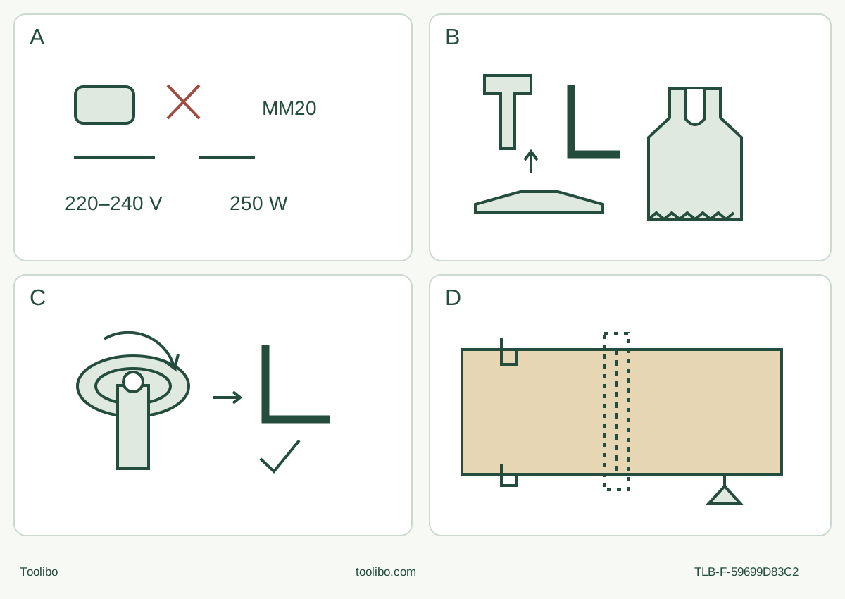
A · Establish the exact isolated body
Match UK 220–240 V, 250 W MM20 and the supplied document. OFF, full stop and unplug before handling; no battery action.
B · Keep the original clamp parts
Use the provided key, original screw and original washer. In the holder-up source view the washer bevel is up. Remove the old cooled open-slot accessory before seating the original replacement.
C · Complete tightening and remove the key
All matching pins must engage and the blade must lie flush. Securely tighten with the key, check isolated retention and remove the key before any power connection; no numeric torque or powered test.
D · Qualify the whole sample
Clamp retained stock and separately support waste without closing the kerf. Full blade, two-hand, cord and underside clearance plus actual dust controls precede the light cut and isolated acceptance.
Original schematic, not scale or a full assembly drawing. B’s separate parts do not authorize a different stack; follow actual MM20 Figures 3–4. C assumes all original pins engaged flush and the key removed before power. D’s dashed corridor is not a cut-depth dimension or a running fit test.
Match the corded UK MM20 before doing anything else
This is an existing-owner project for the UK Dremel MM20 represented by F013MM20JB and the directly linked WEU instructions 2610Z03546, February 2012. Match the actual body, nameplate, supplied instructions and screw-clamped accessory interface. It is not the cordless MM20V, and the MM40 instructions elsewhere in the same booklet do not describe this tool’s mounting mechanism.
The outcome is a short separating cut in a known dry, untreated, uncoated loose piece of solid softwood, followed by an isolated acceptance decision. Use a positively identified original Dremel MM480 wood blade suitable for the actual material, with enough usable reach for the complete cut. The current UK product names MM480 and the actual manual chart includes it. Neither fact proves that a blade in your box is that original accessory, or promises the contents of a current kit.
No stock thickness is prescribed here. Choose a sample whose actual blade reach, complete movement envelope, clamping, separate waste support and two-hand access can all be established. Both faces and the underside must remain visible. This is not an installed-trim, hidden-service or structural-cut procedure. Missing identity, damaged hardware or an unworkable support arrangement means hold before power is connected.
Qualify the supply, condition and work area
The matched MM20 specifications are 220–240 V, 50/60 Hz and 250 W. Use the actual undamaged supplied UK plug and correct outlet; do not convert plugs, infer a fuse value or copy US electrical information. Check the cord, plug, body, switch, holder, original screw, washer and supplied hex key while unplugged. Cracks, loose or missing parts, damaged insulation, unreliable control or unexplained condition require qualified correction, not a powered trial.
This small bench project should use a suitable outlet without an improvised extension arrangement. If an extension is genuinely needed, the manual requires a completely unrolled, safe 5 A extension; the actual cord, location and electrical instructions must still qualify. Stop if that system is not established. Keep all cords away from the future cut, sharp edges, heat and the operator’s footing.
Use a dry, well-lit and ventilated area with stable footing, bystanders clear and no flammable or explosive atmosphere. Inspect the wood and route for nails, screws, coatings and other foreign material. Do not infer nail-cutting capability from a different blade’s table. A suspect or unknown sample is not a suitable practice piece.
Plan appropriate eye and hearing protection and material-specific dust protection. The machine-specific instructions require a dust mask and dust/chip extraction when connectable for harmful or combustible dust. Establish actual suitable equipment and its complete instructions; do not assume a port alone proves collection. Figure 9 depicts the tool’s dust port with a sanding pad, not a demonstrated saw-blade capture arrangement. Do not transplant a hood or promise cutting capture from that picture.
Before connecting or adjusting dust equipment, slide the tool OFF, wait for complete standstill and unplug it; isolate the extractor under its own instructions as well. Correctly connect, operate and check any chosen dust system under those instructions before cutting. If the actual task’s dust-control requirements cannot be satisfied, postpone the project rather than declaring the small sample harmless.
Change the native open-slot blade while isolated
Slide the switch backward to OFF, wait for complete stop and unplug the tool before any accessory handling. Let an old blade cool and wear protective gloves when changing sharp accessories. Keep fingers away from the teeth and never use the hex key on a powered tool. The booklet’s generic battery/collet wording does not create a battery-removal or rotary-collet action for this corded MM20.
Use the MM20 procedure and actual Figures 3–4, not the MM40 lever sequence:
- With the supplied hex key, loosen the original clamping screw only enough for the native open-slot accessory to slide between the holder and blade washer.
- Remove the cooled old accessory from that space before introducing the new one. Do not stack blades. This project does not invent a closed-ring removal route or require an extra adapter.
- Clean the holder, accessory and clamping screw with a clean cloth. Confirm the original washer is present and correctly oriented: Figure 3’s holder-up view shows its bevel upward, toward the screw head, not reversed toward the holder.
- Place the actual original MM480 between holder and washer. Engage all matching holder pins and make the accessory sit flush against the holder. Choose only a documented orientation that leaves the complete intended route clear.
- Securely tighten the original screw with the provided hex key as Figure 4 shows. No numerical torque or extra washer is invented. Check secure seating while still unplugged, then remove the key before any later connection to power.
An accessory that will not seat flush, a damaged screw or a washer whose identity/orientation is uncertain is a stop condition. Do not tighten harder to compensate, reshape a slot, borrow a screw or run the motor to test retention. Obtain the exact parts or qualified service.
Establish the whole cut, not just tip clearance
Mark a short straight line from an accessible edge. Clamp the retained piece to a stable platform so it cannot rock, slide or flex. Independently support the waste so it does not drop unexpectedly or close the cut onto the blade as separation finishes. Keep clamps and supports outside the entire oscillating blade path, including breakthrough beneath the wood. No person should hold the waste beside moving teeth.
With the tool still unplugged, compare the actual blade and holder position with the marked route. Check usable tooth reach, the entire blade width, retained edges, work support, both hands, the cord and any dust hose. Keep hands away from the sawing area and never reach beneath the cut. If full separation would require twisting the tool, levering the blade, losing support or moving a hand into danger, change the work arrangement or stop.
The safety text requires firm two-hand control and secure stance even though the booklet includes a generic one-hand picture. Use the actual insulated gripping surfaces where the blade could encounter its own cord; keep the cord out of that path and leave vents clear. Do not turn a convenient illustrated hand position into permission to obstruct cooling or hold the work by hand.
Select the documented range and make a light cut
The MM20 slide switch moves forward for ON and backward for OFF. Its variable-speed system covers 10,000–21,000 oscillations per minute. The manual’s ranges are not calibrated promises for every intermediate position: setting 2 corresponds to 10,000–11,000; 4 to 11,000–13,000; 6 to 13,000–16,000; 8 to 16,000–19,000; and 10 to 19,000–21,000 OPM.
For the original MM480, chart 5 gives 8–10 in the softwood column. Use that actual row with the known sample and complete instructions; do not borrow another material’s row or a US MM35 initial-entry recipe. Preset the choice while OFF and unplugged. A setting cannot make a damaged, unidentified or unsuitable blade acceptable.
After all assembly, workholding and dust checks, ensure the switch is OFF and the key is removed before connecting the correct supply. Hold the tool securely with both hands, blade clear of the work, and start it. Establish stable operation before bringing the blade lightly to the marked edge. Allow the accessory and speed to do the work, guiding with very light pressure and repeated shallow passes as needed. Do not force the blade, twist it in the cut or use it as a lever.
Movement of the stock or support, binding, abnormal vibration, smoke, damage or uncertain retention requires stopping. Slide backward to OFF, wait for complete standstill and unplug before investigating; do not reach into the cut, clear a jam while connected or repeatedly restart a suspected fault.
Stop, inspect and accept—or keep the setup on hold
For this project, after complete separation slide OFF, wait for full standstill, then withdraw along the clear path and set down securely. This stop-before-withdrawal order is a conservative project choice, not a quoted special MM20 rule. Unplug before touching the assembly or inspecting the result, let the blade and stock cool, and avoid sharp edges and splinters.
Inspect both faces. Accept only the intended line and full separation, with retained material intact and no uncontrolled tearing, scorching, moved support or unexplained blade marks. No numerical tolerance or finish guarantee is supplied. A remaining bridge is not an invitation to pry with the blade or make a blind extra pass. Reassess the isolated setup; uncertainty or a mechanical fault requires qualified help.
Clean the unplugged tool under its actual instructions. Keep vents and switch areas clear without pushing pointed objects inside, and avoid the solvents identified as harmful to plastics. Internal electrical work and damaged cords belong to qualified Dremel service, not this project. Sanding, scraping, adapters and installed repairs require separately qualified systems; the completed wood sample does not approve them.
Evidence used
Current exact Dremel UK MM20 F013MM20JB product and its actual manual link; shared WEU MM20/MM40 original instructions 2610Z03546, February 2012, complete English pages 8–12/address 13, actual MM20 Figures 1 and 3–5, chart 5, and back page 80. The manual is one shared document, with each model’s distinct mechanism retained. No current availability, kit, US equivalence or hands-on performance claim is made.
Models referenced