
Quick Lock, the selected range and a supported result
A shows a disconnected cord and counterclockwise opening versus clockwise closure of the integrated lever. B shows neutral flush accessory engagement without counted pins. C shows forward/back slide directions and the selected wood range. D shows two grip highlights, clamped retained wood, independent waste support and a blade clear through the sample.
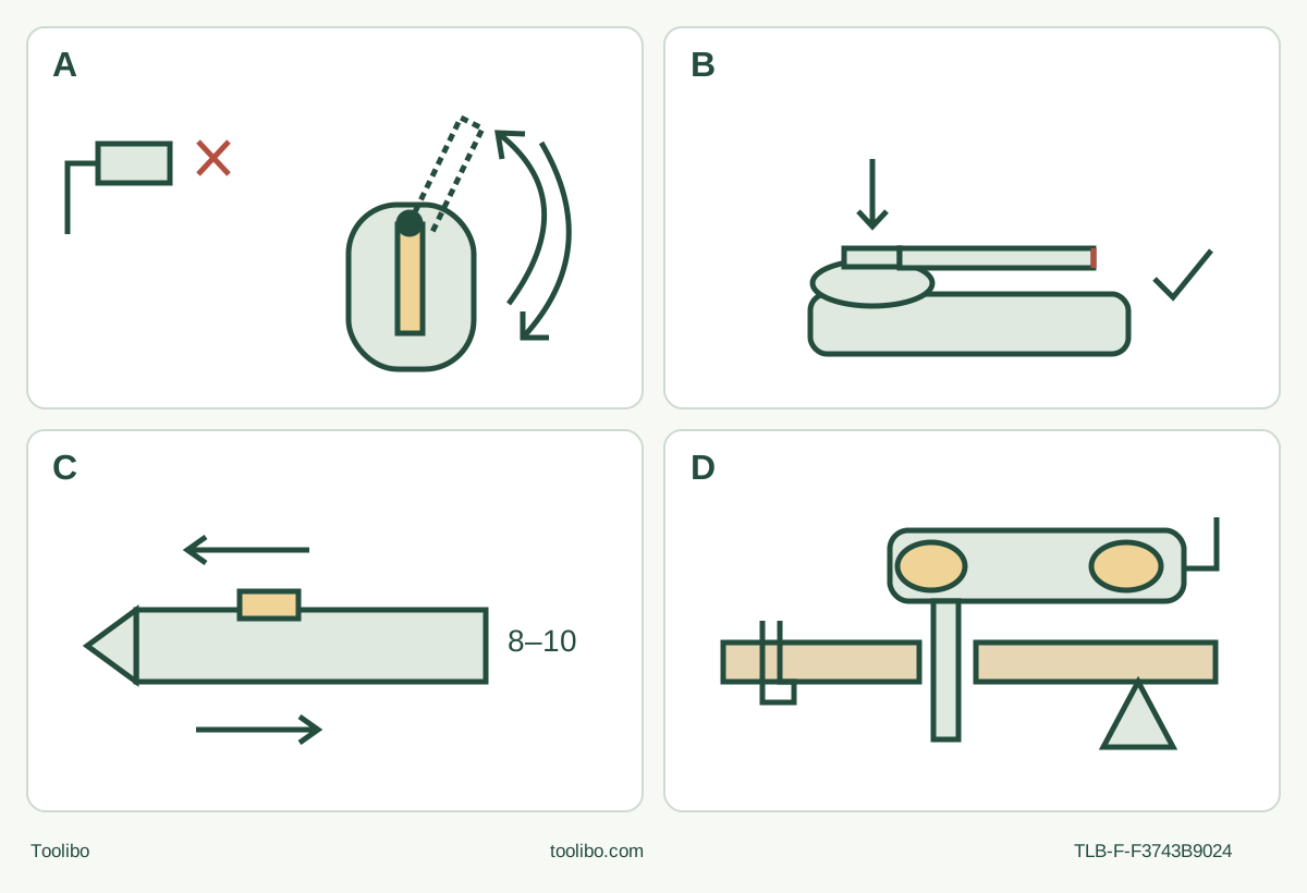
A · Isolate before the lever
Slide backward OFF, wait full standstill and unplug. Counterclockwise fully opens; clockwise fully closes. Keep fingers out of the pinch zone.
B · Engage all pins flush
Remove the old accessory, clean the original parts and fully seat the identified blade. Close the lever and check while isolated; no extra screw/key or final hand-threaded step.
C · Use this blade’s wood row
The actual UK MM480 softwood chart gives 8–10. Slide forward starts and backward stops; do not transfer another model’s speed or control sequence.
D · Complete and isolate the sample
Both hands, vents clear, retained clamp and independent waste support. For this project, stop fully before withdrawal, unplug and inspect complete separation.
Original conceptual schematic. Lever arrows refer to the top view; check the actual MM40 and keep fingers clear of its pinch zone. B does not approve a generic interface. C applies 8–10 only to the identified MM480 softwood row. D is a support and clearance cue, not a depth or performance claim.
Match this UK MM40 before setting up
This is an existing-owner project for the UK Dremel MM40 associated with order F013MM40JB and the linked WEU manual 2610Z03546, 02/2012. Match the actual 220–240 V, 50/60 Hz, 270 W nameplate, supplied instructions and Quick Lock controls. The MM40-1/9 kit name is not another mechanical model. A similar-looking US tool, another Multi-Max or an unresolved document mismatch is outside this procedure.
The outcome is a short, complete separating cut in dry, untreated, uncoated loose softwood, with both faces and the blade exit visible. After stopping and unplugging, you will decide whether the sample is acceptable or the setup needs correction. This is not installed-trim work, a hidden-service cut or a promise of cutting depth, speed or finish.
Use a positively identified original Dremel MM480 with its own applicable instructions. The exact UK product identifies that blade as a wood flush-cut accessory, and the actual front chart on manual page 5 includes MM480, with 8–10 for its softwood column. The shorter application list later in the manual does not erase that row. Do not borrow a US accessory-rating rule, substitute a similar part or assume the current advertised package proves what an older owner actually has. Missing identity, unsuitable material or inadequate usable reach means hold the cut.
Prepare a safe visible route and actual dust controls
With the plug disconnected, inspect the lead, supplied plug, housing, switch, Quick Lock lever, clamping flange and holder. Damaged wiring, cracks, bent or loose parts, an unreliable switch or an unexplained condition require qualified correction before use. The original unmodified plug must match the actual UK outlet and supply. Double insulation does not make damaged wiring safe, and this guide does not include plug conversion, fuse selection or internal repair.
Prefer an appropriate accessible supply without an unnecessary extension. If an extension is needed, the exact manual requires a completely unrolled, safe cord with a 5 A capacity; the actual extension’s own instructions and conditions still apply. Keep the whole cable outside the blade envelope, away from heat, oil and sharp edges, and arranged against snagging or tripping.
Choose a dry, stable, well-lit place away from flammable liquids, gases and explosive dust. Keep children and bystanders clear. Examine the stock and full cut route for nails, screws, staples and other foreign material. Exclude unknown coatings, treated wood, wet stock and uncertain dust hazards. Clamp the retained portion to a stable bench and independently support the waste so it can separate without closing the kerf. Check both faces: clamps, supports and the bench must stay outside the complete oscillating path and breakthrough space. Never use your hand or body as the workholding device.
Wear eye and hearing protection and suitable clothing, with hair, jewellery and loose fabric kept away from moving parts. Follow the actual material information and exposure requirements. For harmful, combustible or explosive dust, the manual calls for a dust mask and dust/chip extraction when connectable, not an invented choice between them. Protect nearby people as well.
Before connecting or adjusting dust equipment, keep the tool OFF, wait for full standstill and unplug it; isolate the extractor under its own instructions too. Positively qualify the actual equipment and connection for the task, then operate and check that system under its instructions before cutting. The manual’s Figure 9 depicts a port and vacuum adapter with a sanding assembly. It does not establish that this assembly captures this saw blade’s dust. Do not improvise a hood or assume another model’s connection. If suitable task dust controls cannot be established, stop rather than using a dusty trial as a test.
Change the native blade using Quick Lock only
Slide the actual ON/OFF switch backward to OFF, wait for complete standstill and unplug. Retain control of the disconnected plug. Let a used accessory cool and wear protective gloves when changing it. Gloves do not permit reaching near a moving blade.
The manual contains generic battery and collet wording, but this selected MM40 is corded. Its isolation is unplugging, not removing an imaginary battery. Its integrated Quick Lock mechanism also differs from the MM20 screw and hex-key procedure printed beside it.
Hold the isolated tool upside down so the accessory cannot fall unexpectedly. Turn the top Quick Lock lever counterclockwise to its fully open position. If an old accessory is fitted, lift its attachment bracket off the holder pins and remove it, avoiding its sharp edge. Do not stack a new blade over an old one. Clean the accessible holder, accessory and clamping flange with a clean cloth; stop if damage or contamination prevents proper seating.
Place the original MM480 in the intended working orientation, engaging all holder pins and seating the accessory flush against the holder. A partial engagement or a blade held up on a pin is not acceptable. If an angled orientation is useful, it must still meet the same full-engagement and clearance requirements. No pin count, universal-fit claim or adapter approval is inferred here.
Firmly control the lever and turn it clockwise into the fully closed position to lock the accessory. Keep fingers out of the space between the lever and body: it is a pinch point. This lever closure is the MM40 clamping action. There is no separate loose screw, washer, hex key or final hand-threaded tightening stage to import from another tool. Check secure flush seating while unplugged. If the blade shifts, rocks or cannot be positively locked, do not run the tool to see whether it settles; obtain the correct instructions or qualified service.
Inspect the entire blade for cracks, deformation, breakage, dullness or other suspected damage before use. Reject questionable accessories. With power still disconnected, compare its actual usable reach and complete oscillating envelope with the supported sample. Leave clear space for full breakthrough and a safe stopped exit. The sample’s chosen dimensions are a project decision, not a manufacturer capacity rating.
Select the documented range and make the cut
The tool has ten dial positions and a total no-load range of 10,000–21,000 oscillations per minute. Its page 12 table gives ranges rather than an exact calibrated speed for every intermediate position: 2 corresponds to 10,000–11,000; 4 to 11,000–13,000; 6 to 13,000–16,000; 8 to 16,000–19,000; and 10 to 19,000–21,000. For the positively identified MM480 and selected softwood, use the exact page 5 8–10 guidance. Do not convert it into a universal setting for other blades or materials.
Preset with the tool OFF and unplugged. The manual recommends practising on scrap to understand the accessory’s action. This visible sample is that bounded practice, not a licence to test uncertain hardware, supply or dust control. Verify the switch is OFF, the lever securely closed, the blade sound, the stock secure, the waste independently supported and the cord clear before reconnecting.
Hold the tool firmly with both hands, maintain secure footing and keep its ventilation openings clear. The explicit machine-specific two-hand instruction governs even though the generic familiarisation picture shows one hand. Keep hands and body outside the sawing path and never reach beneath the stock.
With the blade clear of the wood, slide the switch forward to ON and establish controlled running. Bring the accessory lightly to the marked route. Let the correct blade and its speed do the work; use very little feed pressure and a series of shallow passes rather than forcing the whole cut at once. Maintain visibility and support through separation. Do not twist the blade to steer, lever out waste or use a stalled tool as a cutting method.
If stock moves, the waste starts trapping the blade, visibility disappears or operation becomes abnormal, stop. Do not clear debris, reposition supports or touch an accessory while it moves. An unexplained mechanical or electrical symptom is a reason for isolated assessment and qualified help, not repeated powered trials.
Stop and judge the isolated result
For this project, slide the switch backward to OFF, wait for complete standstill, then withdraw along the clear path and set the tool down safely. This stopped-before-withdrawal order is the conservative sequence chosen for this visible sample, not a quotation of a model-specific withdrawal rule. Unplug before touching the accessory or inspecting the work, and let hot parts cool.
Accept the sample only if it is fully separated along the intended line and size, without uncontrolled tear-out, scorching, shifted workholding or evidence that a support trapped the blade. No numeric tolerance or finished-joinery guarantee is implied. A poor result needs a documented correction to blade condition, approach, support or dust control before another sample; unresolved holder, switch, supply or identity problems need qualified service.
Clean accessible surfaces while unplugged. Keep vents and switch areas free of loose debris without poking objects through openings or using damaging solvents. Protect the cord and sharp blade in storage. Internal wiring, adjustments and repair belong to qualified service using the correct parts. Record the model, nameplate and exact manual revision for that handoff; neither a successful short cut nor an old warranty paragraph proves current condition or coverage.
Source basis: current UK Dremel MM40 F013MM40JB product identity and direct manual link; WEU MM20/MM40 Original Instructions 2610Z03546, 02/2012, full English pages 8–12, MM40 figures 2 and 6–8, and accessory chart page 5. MM20 mounting instructions are not this project’s procedure.
Models referenced