
Four checks on one hypothetical length budget
Four panels show A a hypothetical 1000 mm raw length with 10 mm end loss; B finished lengths 400, 300 and 250 mm separated by three 3 mm kerfs; C total consumption 969 mm; D remainder 31 mm.
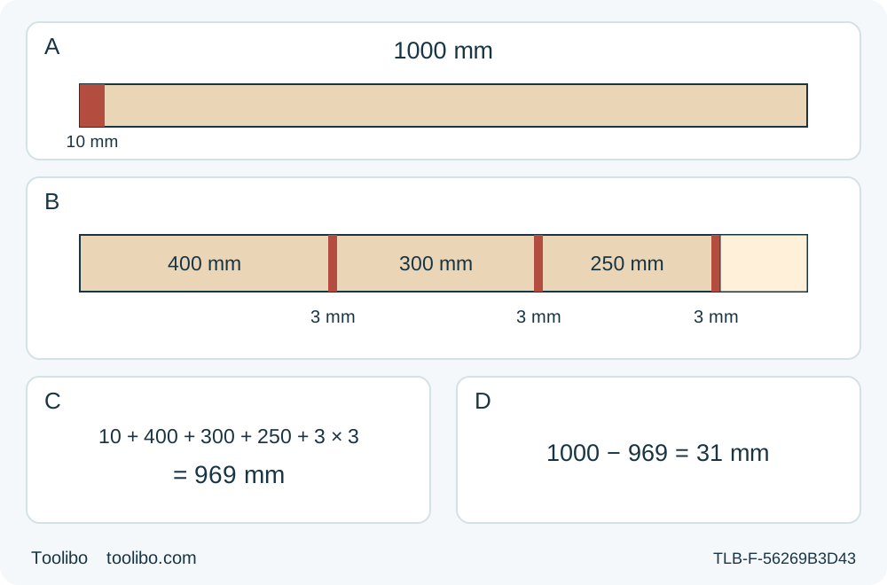
A · Establish the datum loss
Measure raw stock and record the complete end-preparation loss, including its own kerf.
B · Count later separation bands
Keep each finished length and place all three hypothetical 3 mm kerfs outside the retained boundaries.
C · Reconcile consumption
The hypothetical end loss, finished lengths and later kerfs total 969 mm without counting the first kerf twice.
D · Qualify the remainder
The hypothetical remainder is 31 mm; support feasibility and final measured fit remain independent acceptance gates.
Not to scale and not a cutting sequence. All dimensions are editorial examples, not manufacturer specifications or Toolibo measurements. A includes the end-preparation kerf within 10 mm; B adds only the three later kerfs. The 31 mm accounting tail does not establish a safe handhold or executable last cut. No saw handedness or operating direction is depicted.
The deliverable is a feasible layout, not a cutting order
A cut list becomes useful only when its finished pieces, actual saw kerfs, end preparation and remaining stock all fit the same measured length. This guide produces a dimensioned worksheet, a marked retained side for every boundary and a final acceptance record. It does not tell you to cut a short tail while holding it by hand, or to perform the rows in table order.
The operating reference is an already qualified US Makita 5007MG matching instructions 884671-946, with its approved blade correctly installed. Apply the complete owner guide, “Makita 5007MG supported end cut,” the guide “Verified straightedge offset,” and the large-panel support guide before any real cut. This exercise is limited to square, edge-start cuts in known dry, untreated wood. Width, thickness, blade suitability, grain direction and stable support must also be suitable; passing the length arithmetic alone proves none of those things.
Every example dimension below is an invented editorial number. It describes neither a stock item for sale nor a manufacturer kerf, tool offset or promised tolerance. Replace the whole example with measurements from your own qualified setup.
Measure the kerf rather than reading the blade plate
Kerf is the band of material actually removed. Blade-plate thickness, a remembered nominal tooth width and the centre of a pencil line are not substitutes for the cut produced by this blade in this material. Set and lock the intended square-cut configuration first; a changed blade, bevel, guide-contact face or unreliable cut invalidates the previous calibration.
Use a generous disposable sample with the retained work clamped and both sides adequately supported outside the blade path. The offcut must remain free to separate without closing the kerf or pinching the blade. Do not create a narrow strip just to make it easy to measure. Record the sample’s original length between two sound end references. After one qualified complete separation, switch OFF, wait for complete standstill and unplug before collecting either piece or measuring. Preserve both original end references.
Measure both resulting pieces along the same reference edge. The effective kerf is original length minus the sum of the two remaining lengths. Repeat the measurement at another sound edge to expose a skewed cut, and confirm with another generous sample if the result is not consistent enough for the required fit. Do not average away taper, torn ends or a guide that moved.
A hypothetical notebook entry might read: original length 600 mm; remaining pieces 240 mm and 357 mm; therefore 600 − 240 − 357 = 3 mm. A second hypothetical entry of 600 − 238 − 359 = 3 mm agrees. These are arithmetic examples, not results of Toolibo testing. Your worksheet must use your actual measured kerf, with precision justified by the measuring method and the acceptable fit. If a reliable value cannot be established, the layout is on hold.
Separate end loss from separation cuts
Write down four quantities before marking finished pieces:
- L: actual raw length along the chosen straight reference edge, not a catalogue or nominal dimension.
- T: the complete length lost while establishing the starting datum. In this worksheet, T includes the kerf of that end-preparation cut as well as the discarded end material.
- P: each required finished length, with quantity, identity and any agreed finishing allowance stated separately.
- n and k: the number of later real separation cuts and the measured kerf assigned to each of those cuts.
With one common kerf, the unallocated tail is R = L − T − sum of P − n × k. If different cuts require separately measured kerfs, subtract their individual values instead. An extra trim, defect removal, sacrificial test or later fitting cut must be charged to the stock once, not hidden in “waste.” Conversely, do not add the end-preparation kerf again when T already includes it.
Count actual cut bands on a sketch. Three pieces cut away from a continuing remainder require three later separation cuts in the example below, not two. A layout using an already acceptable far end as the last finished edge may have a different count, but that is a different verified map. Do not reduce the count simply because a familiar formula says “number of pieces minus one.”
The end allowance must be sufficient to establish a genuinely square, sound datum. It is not automatically 10 mm. If inspection requires more material to be removed, change T and redo the map before using the remaining length.
Work the complete hypothetical list
Suppose an imaginary board measures L = 1000 mm along a suitable reference edge. The planned starting-datum loss is T = 10 mm including its own kerf. The finished list is one piece each of 400 mm, 300 mm and 250 mm, with no additional finishing allowance. Suppose the actual-setup worksheet has established k = 3 mm; that value is hypothetical here. Three later separations are required, so n = 3.
The required length is 10 + 400 + 300 + 250 + 3 × 3 = 969 mm. The unallocated remainder is 1000 − 969 = 31 mm. There are 4 real cuts in this particular map: one to establish the datum and three later separations. Only the three later kerfs appear in n × k because the first kerf is already inside T.
After establishing and measuring the new datum, the available length must actually be 990 mm for this exact example to remain valid. The following coordinates start from that new datum, not from the discarded raw end. They are a bookkeeping map, not a mandated order of work or an assertion that the drawing is to scale.
Swipe or scroll horizontally to see all columns.
| Region | Start from new datum | End from new datum | Length charged |
|---|---|---|---|
| Finished piece A | 0 mm | 400 mm | 400 mm |
| Separation kerf | 400 mm | 403 mm | 3 mm |
| Finished piece B | 403 mm | 703 mm | 300 mm |
| Separation kerf | 703 mm | 706 mm | 3 mm |
| Finished piece C | 706 mm | 956 mm | 250 mm |
| Separation kerf | 956 mm | 959 mm | 3 mm |
| Unallocated tail | 959 mm | 990 mm | 31 mm |
The three finished lengths total 950 mm, the later kerfs total 9 mm, and 950 + 9 + 31 = 990 mm reconciles the prepared stock. A requested reserve of 40 mm would not fit: 31 mm is short by 9 mm. Do not silently shorten a finished part to make that requirement disappear. Revise the material allocation or the approved design.
The 31 mm tail is only an accounting remainder. It is not a recommended handhold, a minimum safe offcut or a promise that the last separation is physically practical. If clamps, guide engagement, broad base support or free offcut separation cannot be maintained, this layout is not executable even though the sums balance. Allocate more stock or choose another qualified method; never rescue the arithmetic by holding a short piece in your hand.
Transfer finished boundaries without losing the retained side
Label each part and its datum before separation removes the shared reference. In this example, mark the finished boundaries at 400 mm, 703 mm and 956 mm from the prepared datum, and mark the kerf bands immediately beyond those boundaries in the direction of increasing coordinates. Label the retained part adjacent to each boundary. A single unlabelled line cannot communicate which side must survive.
Use one reference edge and a checked square to transfer each boundary across the intended cut. Recheck the marks with an independent reading before clamping the guide. Do not lay out the next finished part from an indistinct sawdust edge or repeatedly add rounded numbers to the previous pencil line. If cutting changes the accessible datum, measure the actual new edge and reconcile the remaining map before proceeding.
The map locates the finished edge; it does not locate the guide face. Use the separately verified base-edge-to-retained-cut offset for the actual safe guide arrangement. The straightedge-offset guide explains why an offset calibrated to the retained edge already accounts for that boundary: adding another half-kerf would move the finished edge. Do not transplant its illustrative offset or reverse the tool’s support geometry to make this worksheet fit.
Keep the broad base on solidly supported wood, secure the work and guide, and keep supports and clamps out of the path. Larger panels need support on both sides near the cut and near their outside edges. Complete the owner’s blade, guard, depth, bevel, cord, eye/hearing protection and dust checks. This worksheet adds no permission for plunge cuts, unsupported narrow pieces or turning a moving blade back toward a missed line. Stop and isolate before a layout correction.
Close the worksheet with measured fit
After each permitted separation, wait for complete standstill and unplug before handling the parts or making adjustments. Check the retained piece at two separated positions against the required length and check squareness. Record actual results beside the target rather than declaring success from the layout marks alone. Inspect edge damage that may consume a fitting allowance; a part can measure correctly at one corner and still fail its intended joint.
Use the agreed drawing or a safe, unpowered mating-part fit check to accept each piece. No universal tolerance is supplied here. A too-short piece is not restored by remarking it; mark it rejected for that purpose. A deliberately oversized piece needs a separately qualified finishing plan and another material budget, not an improvised shaving cut.
The completed record contains the tool and blade identity, material and thickness, reference edge, measured kerf evidence, raw length, actual end loss, required dimensions and allowances, actual cut count, retained-side map, reserve and final measured fit. Mark the result accepted for the stated use, replan before cutting, or part rejected. The source basis is Makita 884671-946, printed pages 3–8, for isolation, support, guiding and operation; the equations and example are original planning arithmetic, not manufacturer specifications or hands-on performance evidence.
Models referenced