
One datum, one guide contact face and one retained cut edge
An upward-feed conceptual plan shows datum A on the left, retained-side straightedge B, base-to-cut interval C and waste D on the right. Illustrative dimensions show 300 mm finished width minus 100 mm verified offset equals 200 mm guide position.
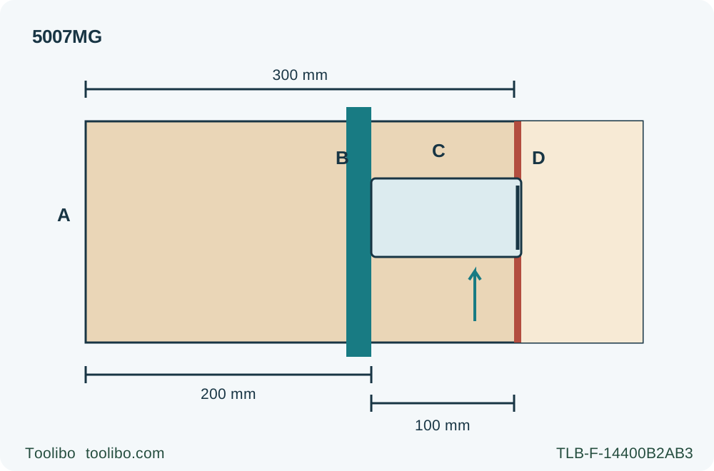
A · Datum edge
Use a straight verified edge and measure from the same datum at both ends.
B · Guide contact face
Position the face that actually touches the base, not the guide centre or opposite face.
C · Verified offset
After the sample cut, wait for standstill, unplug and measure this distance; recheck after blade, angle or contact-side changes.
D · Waste-side kerf
Preserve the finished-width boundary; place removed material on the waste side and verify a second sample.
An isolated layout, not an operating photograph. The upward arrow gives an operator-right blade with broad retained support and guide to the left. All three dimensions are illustrative: 100 mm must represent an actually measured offset, not a 5007MG factory value. Measure the 200 mm placement to the guide face touching the base; 300 mm ends at the retained cut edge, and the kerf extends into waste D. Clamps and work supports are omitted for clarity but remain mandatory as described.
The outcome: place a guide from a verified cut edge
A straightedge controls the saw’s path, but it does not automatically put the cut on your pencil line. The missing quantity is the distance from the base edge that actually touches the guide to the retained-side edge of the cut made by the installed blade. This workflow establishes that offset on a disposable sample, then uses it to position a guide for a chosen finished width.
The worked model is an existing US Makita 5007MG matching shared manual 884671-946, with a correctly fitted approved wood blade and all normal operating checks already satisfied. Makita requires a rip fence or straightedge guide when ripping and instructs the operator to keep the wide part of the base on supported retained wood. The measuring method below is an editorial layout exercise built on those requirements—not a factory-specified 5007MG offset, an approved track system or a replacement for the complete owner instructions.
The finished outcome is a recorded guide-contact edge, verified offset and acceptable test strip. Changing the blade, bevel angle or guide-contact side invalidates that record until checked again. This exercise is for square, edge-start cutting of known dry, untreated wood; it excludes internal plunge cuts, bevel offsets and loose narrow strips that cannot be supported safely.
Define three edges before measuring anything
First identify a straight, trustworthy datum edge on the workpiece. Finished width will be measured from that datum to the retained cut edge. A rough, bowed or tapered edge cannot become a reliable datum merely by taking more measurements from it.
Second identify the straightedge’s contact face—the edge against which the chosen side of the saw base will slide. Measure to that face, not to the far side or centre of a thick guide. The guide must be straight, rigid and tall enough to engage the base without touching the motor housing or guard. This is not permission to fit the saw directly to an unrelated guide rail.
Third identify the retained-side boundary of the blade’s kerf. The kerf is the material removed by the teeth, not merely the thin blade plate. To preserve a marked finished width, the removed band belongs on the waste side of that boundary. Using the plate centre or a guessed half-kerf correction can leave an accurately guided cut on the wrong side of the finished dimension.
For the illustrated arrangement, the guide is on the retained side, the broad base is left of the blade, and forward travel is upward. The blade and waste are on the operator’s right. The figure is a conceptual top view of an isolated layout, not a picture of hands operating a saw.
Qualify the guide and support while unplugged
Switch off and unplug before setting depth, moving clamps or measuring near the tool. Confirm the trigger returns to OFF, the original blade assembly is suitable and sound, and the lower guard moves freely and closes immediately. With the saw isolated, also verify that the guard clears the blade and other parts at all angles and depths of cut. The 5007MG lamp is on whenever plugged in; light is not proof of isolation. Its blade coasts after trigger release, so do not approach a measuring point until it has stopped and the plug is disconnected.
Set and lock zero bevel. The positive-stop selector is not the bevel lock. Set the depth for the actual stock and securely tighten the depth lever; this manual permits no more than one blade tooth below the work. Check the real projection rather than relying on a remembered scale setting.
Choose a generous sample large enough for the wide base, guide and clamps without a hand holding the stock. Support the retained region stably, and support larger panels on both sides near the cut and near their outside edges so that sagging does not close the kerf. Keep supports and hardware out of the blade’s path. The offcut must separate without dragging the retained work or trapping the blade.
Clamp the guide firmly at both ends where the clamps cannot obstruct the base, motor or handles. With the saw disconnected, check the contact edge and available path at entry and exit. Do not push the guard forcibly through the stock as a rehearsal. Allow the base to meet the guide before the blade enters, and maintain useful guide contact through the finish. If the guide is too short or a clamp blocks either end, change the setup rather than improvising midway through a cut.
Establish the offset on a disposable sample
Begin with a provisional layout comfortably away from the sample edge, so an inaccurate first placement will not create a narrow unsupported strip. You may compare the isolated base and blade position to estimate whether the layout has enough room, but do not treat an awkward ruler reading against tooth tips as the final calibration. The sample cut supplies the actual retained edge.
Mark or record the guide contact face’s position from the sample datum at two separated points, ideally near each end of the intended cut. Use the same measuring reference at both points. These measurements also reveal an unintentionally skewed guide before cutting. Tighten the clamps, then recheck: clamping pressure can move a guide that was correctly positioned while loose.
Complete the normal operating setup: eye and hearing protection, appropriate dust precautions, clear cord route, both front and rear grips and balanced body position out of the blade’s line. With the base flat and the blade clear of the wood, connect power, start and wait for full speed. Advance gently along the guide, keeping the base’s chosen edge in contact without twisting or forcing it sideways. The guide directs a controlled feed; it does not correct poor support or a dull blade.
After the blade clears the work, release the trigger, wait for complete standstill and confirm lower-guard coverage before placement. Unplug. Do not touch the fresh edge, offcut or guide clamps while the blade is moving.
Measure from the datum to the retained cut edge at the same two stations. At each station, subtract the previously recorded datum-to-guide-contact distance. The result is the actual offset for this blade, zero-bevel setting and selected base edge. Alternatively, where access is clear and safe, measure directly from the still-clamped guide’s contact face to the retained cut edge after the saw is removed and disconnected. Neither method requires reaching around an exposed blade.
Use the offset without moving the kerf onto the good side
For the illustrated retained-side guide arrangement:
Guide-contact position from the datum = desired finished width − verified offset.
The picture’s numbers are deliberately illustrative. If the desired retained width is 300 mm and your actual verified offset happens to be 100 mm, place the guide’s contact face 200 mm from the datum. These are not Makita factory dimensions. Do not set an unmeasured 5007MG to “100 mm offset” merely because the diagram uses it.
The 300 mm finished line is the retained edge, while the kerf extends into the waste beyond it. Do not subtract another half-kerf after calibrating to that retained edge: the sample has already established where that edge lies relative to the guide. Conversely, an offset measured to the blade plate centre is not the same quantity and must not be substituted in this equation.
Mark the calculated contact-face position at both ends of the next layout, align the guide, clamp it and remeasure. A straight guide can still produce a tapered strip if its two positions differ. Check that the resulting guide location leaves enough retained material for support and that the saw can reach the line without motor, guard or clamp interference. If the desired width is too small for this arrangement, choose a different qualified method rather than reversing the base or holding a narrow piece by hand.
Accept the second sample before committing valuable stock
Make another disposable test using the calculated placement and the same controlled start, feed and stop sequence. After standstill and disconnection, measure its finished width at two separated points and check the cut’s straightness and square edge. Agree on the required fit or tolerance before judging the result; this article does not promise a universal machining tolerance from a hand-held saw.
If both measurements miss the target by a similar amount, revisit the offset, the chosen guide face, the retained-versus-waste interpretation and the reading technique. If the errors differ along the cut, investigate guide skew, flex, clamp movement or loss of base contact. Do not automatically “correct” both kinds of error by adding an arbitrary millimetre to the formula.
A shifted clamp, rubbing guard, burning, abnormal vibration or binding rejects the setup even if a single width reading looks good. If binding occurs, release the trigger and hold the saw still until the blade stops; never pull a moving blade backward or steer it forcibly back against the guide. Unplug before finding and correcting the cause. Persistent defects require appropriate tool or blade assessment, not repeated forced trial cuts.
Record the model, installed blade identity, zero-bevel setting, guide and contact face, stock thickness, verified offset and accepted finished measurements. Label the value as a tested setup rather than a permanent saw specification. A blade replacement, different guide face, bevel change or impact to the base calls for a new sample. This record is the useful product of the exercise: it replaces guessed offsets with a repeatable, checked layout while preserving the saw’s support and stopping requirements.
Models referenced