
Plan-view support zones and a clear cutting corridor
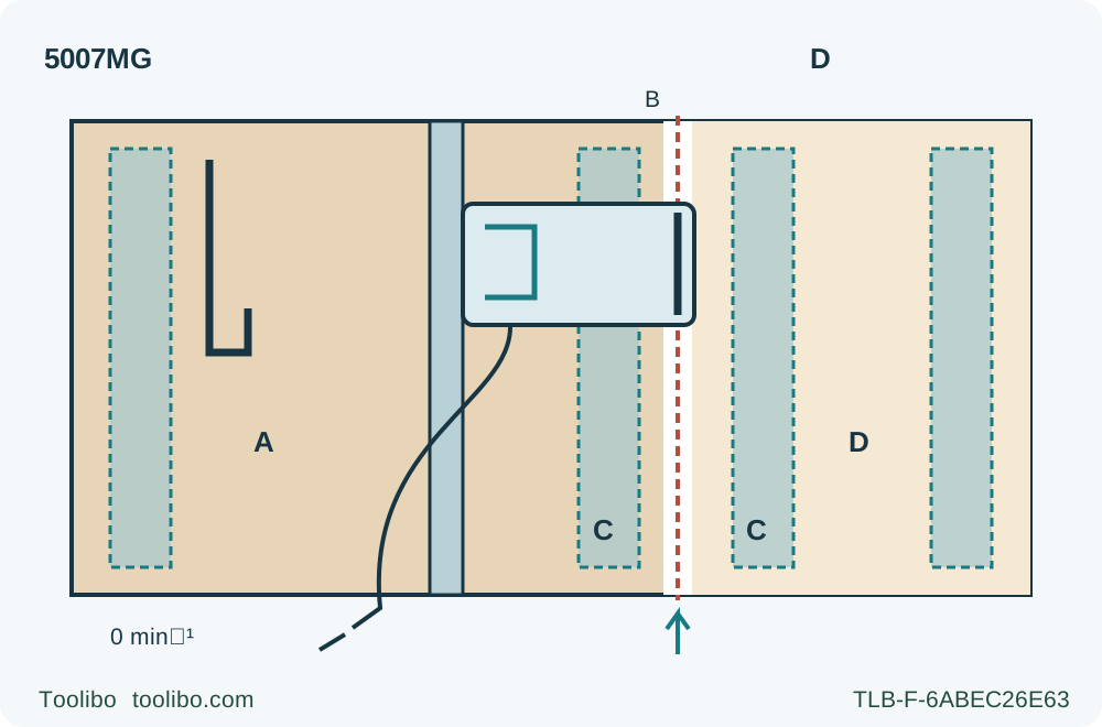
An isolated 5007MG plan shows upward intended travel with the blade at the right of the broad retained base. A labels retained stock, B the clear cut corridor, C near-cut supports on both sides, and D separately supported waste. Outer support zones, a retained-side guide and restraint, and a trailing disconnected cord are also shown.
A · Retain the base support
Choose the retained portion before positioning the guide; keep the wider base over stable supported material through separation.
B · Keep the blade corridor clear
Check below the whole cut, including entry and exit, against the actual locked depth; supports must not intersect the blade path.
C · Support near the cut and edges
Prevent sagging on both sides without treating the schematic zones as fixed dimensions or a load-rated design.
D · Control the offcut without trapping it
Support the waste against dropping or tipping, but do not clamp it inward, close the kerf or plan to catch it by hand.
This is a disconnected, stationary planning schematic, not a running-cut or support-construction drawing. A is the retained piece under the broad base; B is a clear blade corridor with upward intended feed and a right-side blade; C marks support near both sides of the cut, supplemented by outer-edge support zones; D is the separately supported offcut. The shaded zones are below the panel, not a specified number or spacing of structural members. Keep every support and fastener clear of the actual blade projection. The retained-side clamp symbol is illustrative; place real panel and guide clamps outside the whole saw and hand-clearance envelope. The cord trails away from the cut and must not snag. No panel thickness, support rating or underlay material is implied.
Plan for two pieces, not one sheet
A large loose panel can look stable before a cut and become unstable as soon as the kerf divides it. The useful planning question is not simply “Will the sheet fit on these supports?” It is “What supports the retained piece, the offcut and the saw throughout the separation?” This workflow produces a checked support-and-clearance layout, a controlled straight cut and an acceptance record for the resulting pieces.
The worked tool is a Makita 5007MG matching the shared 5007MG/5007MGA manual 884671-946. The support principles come from its correct and incorrect panel-support figures, the wide-base instruction and the operating method. This is not a new model or a claim that every circular saw has the same base geometry. Use an already qualified original blade assembly and the complete matched owner instructions. Blade installation, high-angle cutting, internal plunge cuts and service adjustments are outside this article.
Choose a dry, sound wood panel whose material and condition are known. Exclude unknown coated or chemically treated stock, embedded nails and screws, and material too warped to sit stably. A loose panel is not a floor, wall or installed assembly: this guide does not authorize cutting above concealed services or through anything beneath it. If the sheet cannot be placed, secured and reached without strain or overreaching, stop and arrange a suitable handling method or a different setup before bringing the saw to it.
Mark the outcome before moving the supports
Mark the finished dimension on the portion to retain, then identify the waste side of the cut. Account for the blade’s kerf on the waste side rather than treating a pencil line as a dimensionless path. For a long straight cut, establish a reliable reference edge and a securely clamped straightedge. Verify the actual base-to-cut offset on suitable scrap; there is no universal factory offset for all blades or saws.
Write down which piece will remain under the wider part of the base. The manual directs the wider base onto solidly supported work, not onto the section that will fall away. With this MG’s operator-right blade, an upward-travel plan places the blade and smaller offcut to the right and the broader retained base support to the left. Do not mirror that arrangement from an underside illustration or copy a blade-left saw’s layout.
This does not mean standing in line with the blade or reaching across it. Choose the panel orientation and approach so both designated grips can be used, the body stays aside and the entire planned travel remains accessible. If that is not possible, redesign the setup. A reachable starting position is insufficient if the operator must lean across the sheet halfway through the cut.
Build support on both sides without obstructing the cut
The manual’s correct support figure places support under both sides near the cut and near the panel edges. Its incorrect example leaves a broad unsupported span near the cut. That unsupported span can sag under its own weight and close the kerf around the blade. Two distant sawhorses are therefore not automatically an adequate panel-cutting arrangement merely because the uncut sheet rests on them.
Use a stable support system suitable for the actual panel and intended work. Inspect its condition and follow its own instructions. This article gives no invented load capacity, leg spacing or universal number of supports. The four shaded support zones in the diagram communicate near-cut and outer-edge locations; they are not a construction drawing or a certified four-support design.
Check the top surfaces together. A rocking or twisted arrangement can make one part of the panel carry the load while another floats. Establish stable contact before clamping. Do not try to flatten a badly warped panel by pushing down with the saw or use the cut to release an unknown spring-loaded distortion.
Keep every support clear of the complete blade path beneath the panel, including the entry and exit. “Near the cut” does not mean directly under the teeth. Check the actual projection at the selected depth, the underside of the panel and anything a tooth could reach. Do not leave a metal crossmember, fastener, clamp foot or hidden bench edge under the kerf. This workflow does not prescribe foam, insulation board or any unverified sacrificial underlay to cut into.
Think through the final separation. The offcut needs support that prevents it from dropping, tipping into the blade or levering the retained piece upward. At the same time, supports and clamps must not squeeze the two edges together or close the kerf. Do not plan to catch the offcut by hand. If its size or position cannot be controlled by the support arrangement, change the plan before powering the saw.
Secure the retained panel and guide independently
Support carries the panel; restraint prevents it sliding. Clamp the retained portion to the stable support system using suitable clamping points, and secure the straightedge separately. A guide lying loosely on the panel is not a reliable reference. A hand pressing the panel down is not a replacement for a clamp, and no hand belongs under the sheet to check clearance while the saw is connected.
Keep clamps outside the complete saw envelope, not merely away from the blade line. Include the base, motor housing, front grip, rear handle and the operator’s hand clearance. Check the beginning and end of the pass, where a clamp that appears distant from the blade may still collide with the base or grip. A guide must remain firm without bowing or forcing the saw into a curved path.
Do not bridge the intended kerf with a clamp or tighten the waste against the retained piece. That can defeat the separation the support layout is meant to allow. The offcut must remain stably supported without being driven inward. After tightening, recheck panel contact and the intended cut corridor: clamping can change a previously level arrangement.
The planning diagram omits a running operator and is not a literal clamp-placement template. Its retained-side clamp symbol distinguishes restraint from the shaded supports underneath. Actual guide clamps and panel restraints must be placed and checked for the real equipment, panel and full travel, rather than copied to fixed distances from the drawing.
Check depth, cord and the disconnected travel
Unplug the MG before adjusting or inspecting the setup. Set zero bevel and lock the angle; set depth for the actual panel thickness and lock the depth lever. This exact manual says no more than one blade tooth should project below the work. Check the real projection, not only the scale. Excess depth exposes more blade below the sheet and can reach an otherwise overlooked support; insufficient depth leaves the panel joined.
Confirm the lower guard moves freely and closes instantly, at all angles and depths of cut, including the selected setting. Its spring and retracting lever must work without interference. Ordinary edge-start cutting here relies on automatic guard movement, not a tied-open guard. Stop for a damaged or sluggish guard, uncertain blade mounting or a switch that does not return correctly.
Route the cord away from the cut and from places where it can catch the panel, guide, supports or clamps. Provide enough free travel without loose cable lying under the blade or across the walking route. Check the supply and any extension against the actual nameplate and full instructions; a long panel is not a reason to improvise an undersized extension. The MG’s lamp stays on while plugged in, so lamp behavior is not a trigger-controlled isolation indication.
With the plug disconnected and the blade stationary, check approach, guide contact and clearance through the intended motion without forcing the guard over an edge. Keep fingers away from teeth and do not deliberately expose or drag them through supports. Confirm that both grips remain reachable, the base stays supported and the cord can follow freely. Do not treat the rehearsal as a powered test of whether a support might get cut.
Use suitable eye, hearing and dust protection and ventilation for the known material. The MG’s blower is not dust extraction, and this source does not qualify a hose adapter to add to the tool. If the job’s dust cannot be controlled appropriately, stop and choose a properly documented arrangement rather than improvising an attachment.
Make the pass without changing the support plan mid-cut
Only connect power after the panel, guide, clamps, settings and travel route pass inspection and the trigger is released. Rest the front base on supported material with the blade clear of the entry edge. Hold the front grip and rear handle, start the saw and wait for full speed. Advance smoothly forward with the base flat and the guide contact maintained. Do not push hard enough to slow the blade or twist the saw back toward a wandering line.
Watch for a change in support behavior as the cut progresses: sagging, rocking, a moving guide, a tightening kerf, unexpected resistance or a snagging cord all require stopping, not a faster finish. Release the trigger and hold the saw motionless until the blade completely stops. Never pull a moving blade backward, lift it from the kerf or reach to catch the waste.
Unplug before investigating or moving supports, clamps or the cord. Correct the cause rather than merely freeing the blade. If restarting in an existing kerf is appropriate after correction, the blade must be centered and its teeth clear of the material. An unexplained pinch, displaced support or unstable remaining piece is a reason to rebuild the layout, not to repeatedly restart under load.
At completion, retain control of the saw and the supported work. Release the trigger and wait for complete standstill; confirm the lower guard covers the blade before setting the saw down. The 5007MG does not inherit the 5007MGA’s electric brake. There is no assumed number of seconds after which a hand may approach the offcut.
Accept the pieces and the layout separately
Unplug before removing the guide or handling the separated pieces. Confirm both pieces are stable, then remove them in an order that does not tip the remaining support arrangement. Do not pull one piece free while the other is still being held by a clamp or balanced against it.
Measure the retained width at several points and check the cut against the intended straight reference. Inspect the edge for an uncut underside, excessive tearing, burn marks or steps caused by a pause. Those observations help determine whether the result meets the project’s requirements, but a cosmetically good edge does not prove the setup was acceptable.
Also inspect the process: did a clamp shift, did the offcut drop or rotate, did the kerf pinch, did the base lose support, or did the cord need rescuing? Any of those findings rejects the layout for repetition until corrected. Record the material and thickness, verified offset, depth and support locations that actually worked. Recheck them when the panel size, cut position or offcut width changes. The deliverable is not just one straight edge; it is a support plan that remains controlled from the intact sheet through two separate pieces.
Models referenced