
Plan the support, tooth projection and stopping sequence
A conceptual top view shows upward travel with a right-side blade, retained wood and clamps left, waste right and cord trailing behind; separate diagrams show a 19 mm example board with at most one tooth exposed and a stopped, guarded blade.
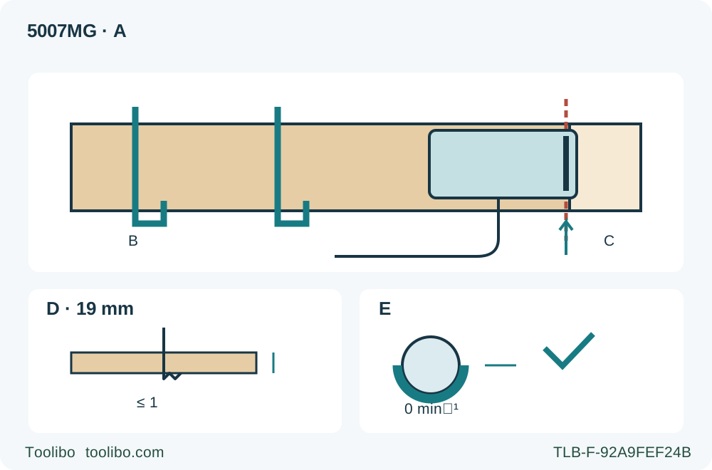
A · Plan the travel
Check the complete path while unplugged; the schematic omits hands, and actual cutting requires both front and rear grips.
B · Retained support
Clamp stable retained wood and keep the wider base supported, with clamps clear of the saw.
C · Waste and cord
Let the waste separate without closing the kerf; keep the cord clear of blade and snags.
D · Actual tooth projection
Set and lock depth for this board: no more than one tooth below it, not an assumed maximum setting.
E · Two stopping checks
Wait for complete standstill and confirm lower-guard coverage before placing the saw down.
An isolated planning diagram, not a running-cut photograph. Upward travel places the blade on the operator’s right; the broad base remains on retained wood to the left, with the cord trailing clear. The 19 mm board is illustrative, not a required thickness. The ≤1 symbol means no more than one blade tooth below the work. Standstill and lower-guard coverage are separate prerequisites; the 5007MG has no MGA electric-brake claim.
The outcome: a controlled square end cut, not just a running motor
This workflow is for an existing US Makita 5007MG whose nameplate, controls and supplied instructions agree with the manufacturer’s shared 5007MG/5007MGA manual, identifier 884671-946. It ends with a short, square offcut from a securely supported wooden board and an inspection of the retained end. It is not a replacement for reading the complete instructions or receiving practical instruction when you cannot confidently support and control the saw.
The final letter matters: the electric-brake instructions in this booklet apply only to 5007MGA. A 5007MG owner must not borrow that feature from the adjacent model. This guide also does not promise a current carton configuration, a particular regional supply voltage, or that the available booklet is the latest revision supplied with every saw.
Use a known, dry, untreated wooden board with enough retained length and width to support the broad part of the base throughout the cut. Inspect it and remove all nails. Product descriptions of nail-resistant blade tips do not authorize cutting through hidden metal. Exclude painted or otherwise uncertain material, internal plunge cuts, bevel cutting and small loose pieces that would need to be held by hand.
Qualify the existing saw before arranging the cut
Switch off and physically unplug the cord. The shared manual specifies a 185 mm / 7-1/4 in blade and 5,800 rpm no-load speed; the US product identifies a 5/8 in arbor. Begin only with the correctly fitted, approved wood-cutting blade and its matching original mounting parts. A matching outside diameter alone does not establish that the bore, ring, flanges and bolt are correct. An uncertain assembly, damaged blade or unsuitable blade rating stops this workflow. Have it corrected using the complete matched instructions or qualified service rather than improvising spacers or following a partial blade-change recipe.
Inspect the cord, plug, base, handles and visible fasteners. With power disconnected, check that the trigger moves properly and returns to OFF when released. This saw starts by pulling the trigger; do not invent a separate lock-off sequence. A trigger that fails to return or cannot control the tool requires repair before use.
Check the lower guard using its retracting lever, then release it. It must move freely and close immediately, without touching the blade or other parts at all angles and depths of cut. The lever must not contact the housing. A sticky guard, weak spring, impact damage or uncertain closure is a stop condition, not a reason to hold the guard open. For this ordinary edge-start cut, the guard operates automatically.
Match the electricity supply to the actual nameplate and use an undamaged, suitably rated extension only when needed. The manual’s cord table depends on both current and length; a lead that merely fits the plug is not automatically suitable. Do not alter the plug. Plan a dry, well-lit workspace, eye and hearing protection, suitable dust precautions and ventilation, with other people clear of the operation. The built-in blower clears the sight line; it is not a dust-extraction system. This manual does not establish an improvised hose attachment.
Make the retained board carry the saw
Mark a square cut line using a reliable square and identify the waste end. Support and clamp the retained board on a stable platform. Keep the broad portion of the saw base on that solidly supported section, not on the piece that will separate. The manual’s end-cut illustration makes this distinction explicitly: a successful layout does not depend on catching the offcut or holding it against the blade.
Leave the complete blade path clear underneath. Supports, bench edges and clamp hardware must not enter that path. The waste must be able to separate without closing the kerf or pulling the retained board over. Larger panels need support on both sides near the cut and near their outer edges; the short-board arrangement is not a universal panel-support plan. If the setup rocks, sags or requires a free hand to steady it, change the setup before connecting power.
Position clamps outside the base, motor and handle travel. Route the cord away from the cutting area and from places where it could snag. Stand with balanced footing and your body to one side of the blade’s line, not directly behind it. Both hands belong on the saw’s front grip and rear handle during cutting. Neither hand holds the work, reaches underneath it or sits behind the blade.
Set zero bevel and a limited tooth projection
Still unplugged, loosen the depth-guide lever, move the base to the required depth and tighten the lever securely. Inspect the actual projection below this board: Makita specifies no more than one blade tooth below the workpiece. Do not substitute a maximum-depth setting for this check. The illustration’s 19 mm board is only an example; it is not a required stock thickness or a universal depth setting.
Set the base to zero bevel and secure the bevel lever. Distinguish that lever from the positive-stop selector: the 22.5°, 45° and 56° selector determines the available bevel range, while the separate lever locks the actual angle. The selector alone does not secure the base, and a selector pointing at 45° does not prove that the base is tilted to 45°. This sample remains at zero; it does not resolve the conflicting high-angle capacity information in other product material.
The front-base A reference is for straight cuts; B is for 45° bevel cuts. Use A to establish the intended straight-cut alignment, but confirm where the installed blade will remove material on a disposable sample. A sight mark is not a guarantee that an unfamiliar pencil-line edge or assumed kerf centre will produce the desired finished length. For a clamped guide, establish the actual base-edge-to-cut offset separately rather than guessing from the base width.
Rehearse the whole path without power
Place the front of the base on the board with the blade clear of the entry edge. With the cord disconnected, rehearse the approach, grip changes before starting and the available travel without forcing the guard into the work. Check that the retained wood supports the broad base, the clamp heads remain clear, the cord has slack and both hands can stay on their intended grips. Do not make a powered “clearance test” to discover an obstruction.
The top-view illustration is a planning schematic, not a photograph of a running cut. Its upward travel arrow puts the blade on the operator’s right and the broad retained support on the left. It does not prescribe a body position directly behind the blade. The separate lower panels explain tooth projection and the two conditions required before setting the saw down.
Cut, stop and put down deliberately
Connect power only after the setup is complete and the trigger is released. The lamps illuminate when this model is plugged in and stay on until it is unplugged; they are not triggered only by cutting. Their light is therefore not evidence that the blade is stopped or the tool is isolated.
Hold the front grip and rear handle firmly. With the base resting flat and the blade clear of the wood, pull the trigger and allow the blade to reach full speed before entering. Advance smoothly forward along the line, keeping the base flat. Do not force the feed, twist the saw back toward a missed line or lift the rear of the base to hurry the finish. Maintain the support and both-hand grip as the blade clears the far edge.
Release the trigger after completing the cut. Wait for the blade to stop completely and confirm that the lower guard covers it before placing the tool down. The 5007MG blade coasts after release; neither a darkening sight line nor a changed motor sound replaces these checks. Never reach for the offcut while the blade is moving.
If the blade binds or the cut must be interrupted, release the trigger and hold the saw motionless until the blade stops. Do not pull a moving blade backward out of the kerf. Unplug before investigating support, alignment, depth or debris. A wandering cut is corrected by stopping and reassessing, not by steering a running blade sideways. Repeated binding, abnormal vibration, a damaged cord or unreliable guard movement ends the session.
Accept the sample, or stop for correction
After stopping, guard closure and disconnection, inspect the retained end with a square. Check the finished length, obvious tear-out and whether the cut stayed straight. Also inspect the setup: a shifted clamp, rocking support or blade mark in a sacrificial support is not excused by an accurate-looking end.
If the result is not square, first check the marked line, locked zero setting, stable support and smooth travel. Do not turn a failed sample into an unplanned base-adjustment or brush-service lesson. The manual directs repairs and maintenance adjustments to the appropriate Makita service route. Clean accessible dust with the tool disconnected, keep the guard area clear and store the saw only after it is stopped and unplugged. Record the accepted blade, stock thickness, depth and guide arrangement so that a later change prompts a new sample rather than an assumption.
Models referenced