
Original assembly, isolated settings and the actual stopping order
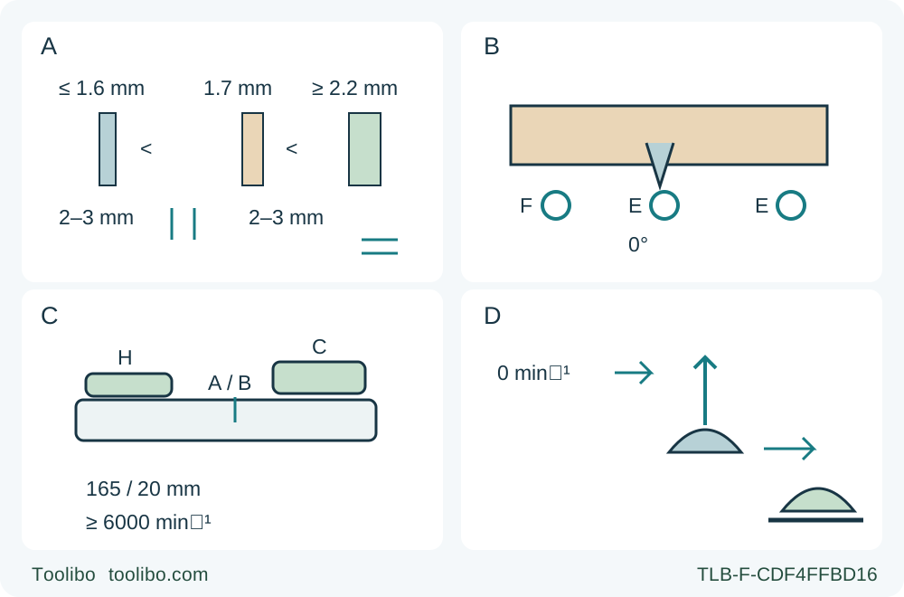
A compares blade plate at most 1.6 mm, knife 1.7 mm and kerf at least 2.2 mm, plus two separate 2–3 mm gap checks. B shows partial tooth projection and distinct F depth and two E bevel locks. C identifies A/B controls and front H/main C grips. D places actual zero rotation before lifting and guarded setdown.
A · Qualify the complete original assembly
Verify blade speed at least 6000 rpm and above tool speed, correct 165/20 mm identity, plate/knife/kerf relation and both 2–3 mm knife gaps. Unknowns hold the task for competent correction.
B · Check actual depth and both locks
Unplug, set zero bevel with both E knobs, secure F and verify actual half-tooth projection. Do not derive a universal setting from the about 3 mm note.
C · Recognize the matched controls
Know front H and main C grips plus A/B start controls under the complete supplied instructions. No improvised interlock sequence or track-only U procedure.
D · Stop before lifting
Release the trigger and wait for full standstill before normal lift. Verify sprung guard coverage before setdown and unplug for inspection; no timed-brake assumption.
This is a non-scale qualification diagram, not a blade-fitting or live cutting pose. A includes both original knife clearances; it does not teach adjustment. B requires actual half-tooth projection, not a universal 3 mm setting. C identifies matched controls only and does not invent A-release/repress timing. D applies after normal completed cutting: release, actual standstill, lift with sprung guard return, covered setdown and unplugged inspection. Binding/interruption instead requires motionless hold until stopped, with no recovery recipe. C groups identifiers conceptually; their spacing is not a physical control-location drawing.
This is an existing-owner workflow for the Canadian DWS520 Type 3 matching DEWALT instructions N394705, marked MAR14. The current Canadian DWS520K product page identifies the DWS520 body and links this exact Type 3 manual. A kit suffix does not establish the contents of your carton, and the same page’s Type 1 download is not interchangeable evidence. Check the physical model, type, nameplate, controls and complete supplied instructions before using this guide.
The completed task is one ordinary, square, edge-entry crosscut in known loose solid wood, followed by dimensional and surface acceptance. The manual’s Figure 9 explicitly depicts that crosscut without a track. This is not an interior plunge: the separate instruction to always use a track when plunge cutting remains in force. No track commissioning, anti-splinter-strip trimming, blade fitting, riving-knife adjustment or trapped-saw recovery is taught here.
Qualify the original blade and riving knife together
Retain only the already correctly installed, approved original wood assembly. The manual specifies a 165 mm blade with a 20 mm bore, rated for at least 6000 rpm; accessory rating must also exceed the actual tool speed. Its supplied riving knife is 1.7 mm thick. The documented matching envelope is blade plate no thicker than 1.6 mm and kerf at least 2.2 mm, so the plate is thinner than the knife and the cut wider than the knife.
Figure 3 gives two distinct 2–3 mm clearances around the knife. These are original-assembly qualification conditions, not an invitation to expose the blade and adjust screws by eye. The knife must be straight, correctly aligned and able to function with the original assembly. Unknown blade identity, missing qualification evidence, incorrect or loose mounting hardware, damage or uncertain knife clearance holds the task for competent correction under complete instructions. Do not infer compatibility from diameter alone or try a different blade to see whether it runs.
Inspect the carbide blade visually before use. Dullness, damage, contamination that impairs cutting, abnormal tool binding or misalignment requires correction before cutting. This guide does not reproduce the manual’s chemical blade-cleaning suggestions, sharpening advice or service procedure. It also does not transfer the current product page’s included 48-tooth description to an unidentified used blade.
Use known clean solid wood with no nails or other foreign objects. The manual expressly excludes solid-surface countertops such as Corian because accumulation can obstruct the plunge return and leave the blade exposed. It also excludes metal, masonry, glass, cement board, tile and plastic. Do not turn a wood sample into permission for those materials or a hidden-wall cut.
Close the supply, dust and personal-protection gates
The actual electrical supply must agree with the saw’s nameplate. The Canadian product lists 120 V and 12 A, but that is not a voltage-conversion instruction or a claim about every regional DWS520. Inspect the cord, plug and extension arrangement. Use the manual’s complete gauge table for the actual voltage, nameplate current and total length; do not select a cable from its appearance or invent a universal extension length. An uncertain or damaged supply is a hold, not an electrical troubleshooting exercise.
Use certified eye protection meeting ANSI Z87.1 or CAN/CSA Z94.3, hearing protection meeting ANSI S12.6 (S3.19), and approved respiratory protection appropriate to the dust exposure, with ventilation. Keep bystanders clear and arrange stable footing and an unobstructed route. Keep clothing, hair and other loose items away from moving parts.
The manual requires the saw always to be connected to a dust extractor designed in accordance with the relevant dust-emission regulations. Verify that suitability from the actual extractor and connection instructions, then operate the system under those instructions before cutting. A hose that is attached to a switched-off or unsuitable vacuum is not a completed dust-control system. The marketing description of a universal 1-1/4 inch port and 90% collection is neither a guarantee nor permission to improvise an adapter. Keep dust directed away from people and foreign objects out of the exhaust opening. The manual requires the exhaust nozzle in the forward or closed position to avoid flying sawdust; verify the actual instructed condition together with the required active extractor, without improvising a nozzle or adapter repositioning procedure.
Route both cord and hose so they remain clear of the cutting area, guide, clamps and moving head for the whole operation. If their movement pulls the saw sideways or interrupts the reach, change the arrangement before starting.
Inspect the guard and recognize the actual controls
Switch OFF, wait for complete standstill and unplug before inspection, setting changes or any adjustment. Check that the guarding system moves freely and encloses the blade instantly, with proper return-spring operation and no contact with the blade or other parts at all angles and depths of cut. A dropped saw needs particular inspection for bent guarding. A guard that binds, closes sluggishly or fails to return is a service hold; never tie or clamp it open or energize the saw to reproduce the fault.
Recognize the main handle C, front handle H, plunge trigger A and on/off switch B. The general switching section specifies using A and B to start; the cutting section separately describes switching on and then lowering using A. This guide does not invent a release-and-repress sequence to reconcile those descriptions. The actual matched controls must be familiar and work under the complete instructions, with the blade clear before it is brought to full speed and lowered into the edge-entry cut. If the required operation is unclear on your actual tool, hold for qualified instruction rather than force, defeat or experiment with an interlock.
The switch has no lock-on provision and must not be tied on. Remove any adjustment key before connecting power and ensure the switch is OFF. The blade-change lock button L and lock lever M are not normal feed controls. The anti-kickback knob U has procedures in the separate track/plunge section; do not import those release/lock steps into this rail-free crosscut or assume off-rail protection from the product’s marketing claim.
Set square cutting and verify actual tooth projection
With power disconnected, loosen the bevel adjustment knobs E, set the shoe D to zero on the bevel scale X and tighten both knobs. Do not tighten only the visible front knob and overlook the rear one. This workflow does not teach the available high-angle settings.
Set depth with adjustment knob F and its pointer, then secure the knob. Verify the actual projection beneath the wood, not just the scale. The general safety text requires less than a full tooth; a later explanation recommends exposing only half a tooth. Use that actual half-tooth condition for this task while ensuring the cut can pass through the material. The separate “about 3 mm” note is not a universal depth setting and must not override the tooth limit for the actual blade.
The manual lists 59 mm without track and 55 mm with track, while the current product gives a 54 mm on-track figure. That difference remains unresolved here. Do not design a limit-capacity task from a synthesized number or transfer an on-track scale interpretation to off-track work. Select a modest sample that can clearly meet the actual depth and support requirements, or hold.
Speed wheel S provides the documented 1750–4200/min range; the table gives settings 3–5 for solid wood. Establish the appropriate setting for the actual approved wood and matched instructions with the tool isolated. This is not a claim that the highest setting is best for every piece, nor permission to use the other material rows as a new application tutorial.
Build the complete edge-entry crosscut layout
Place the good or appearance face down as the manual directs; this does not guarantee both faces will be free of breakout. Mark the desired square line from a verified reference edge, identify the retained side and place the complete measured kerf on the waste side of the wanted dimension. If using a suitable straightedge, its actual base-contact offset must already be established on matching scrap. Do not assume a guide mark is a universal blade-center or kerf measurement.
Secure the loose work to a stable platform. Support the retained piece and offcut near the cut and near the outer edges so neither can sag, drop or close the kerf, while leaving the entire blade corridor clear. Keep the broad base supported on the retained portion. The manual’s crosscut arrangement places the cut to the left; its incorrect illustration shows why a hand must not support the work beneath the saw. Do not copy the unsafe illustration as an operating pose.
Support the free offcut independently without clamping it into a closing cut. Do not catch it, hold a short piece by hand, or rely on a helper near the blade. Inspect below the work for supports and fixtures in the blade path. Any unavoidable base loss, small-piece instability or inadequate clamp clearance holds the sample; no foam or unverified backing is authorized.
Unplugged, check the whole route beside or safely above the line, with the blade guarded and no tooth contact. Confirm front-base support, both grips, lowering clearance, guide and clamp clearance, cord/hose travel, footing and the far-side separation. This is not an unpowered cut or a live trial of a protective feature. Keep the body to either side of the blade, not in its line.
Complete the sample and accept the result
Reconnect only when the layout, original assembly, guard, switch, settings and active extractor are qualified. Hold both the front and main handles at their insulated gripping surfaces. Place the front part of the base flat on the supported retained work with the blade clear. Operate the matched A/B start controls as described above, reach full speed before blade contact, then make the controlled lowering and forward edge-entry feed. Push forward uniformly without forcing, twisting or pulling backward.
Keep hands out of the cutting area and from beneath the work. If the line begins to wander, do not steer the blade sideways. If the blade binds, the saw stalls, the work shifts or the cut must be interrupted, release the switch and hold the saw motionless until the blade stops completely. Unplug and investigate through a qualified process; this owner sample does not teach a restart or extraction sequence for a trapped tool.
At normal completion, release the trigger and allow the blade to stop before lifting the saw from the work. As the saw is lifted, the spring-tensioned guard closes around the blade. Verify coverage before setting down, then unplug before inspection. This is deliberately not another plunge saw’s moving-lift completion rule, and no advertised brake time substitutes for actual standstill.
Measure the finished dimension at both edges, check square relationship to the reference and inspect the face and edge for breakout, burning or damage. Record the wood, actual depth, speed setting, guide contact and dust/support arrangement that produced the accepted sample. A tapered or damaged result is not fixed by forcing a second pass through the same kerf. Hold an unacceptable result for a separately planned correction or qualified service. The completed outcome is a documented, accepted loose-wood sample from the exact original system—not proof of track compatibility, safety immunity or approval for a different material.
Models referenced