
Read, qualify and keep the functions separate
Four conceptual panels show isolated work planning, documentation leading to verification, guard coverage not equal to stopping, and lock-off not equal to disconnection.
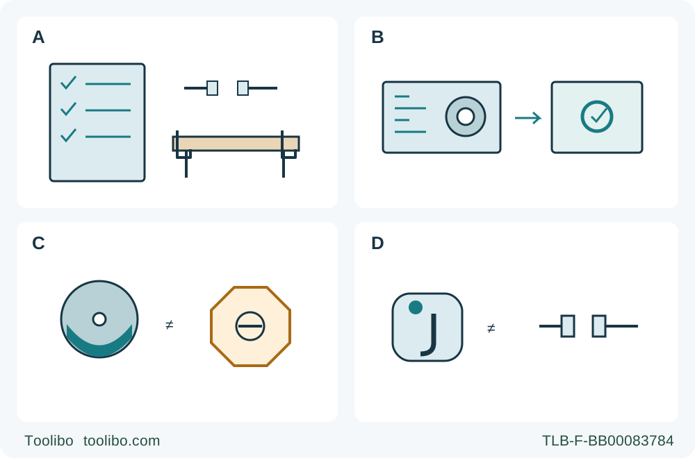
A · Define the complete task
Start with isolated planning, known wood, secure support and the exact machine/manual identity.
B · Record evidence and conditions
For each feature, record its documented action, prerequisites, limits and stop condition; do not count features as points.
C · Guard and stop are distinct
A functioning guard does not prove standstill; a brake does not replace a functioning guard.
D · Lock-off is not isolation
A lock-off reduces accidental trigger action. Disconnect the actual power source before settings, inspection or correction.
A conceptual reading aid, not a mechanical procedure or safety rating. A joins a written checklist with isolated planning and secured stock. B means verify the exact documented system, not award a score. C separates blade coverage from complete standstill. D separates accidental-start protection from physical power disconnection. The symbols do not authorize a live test or replace model-specific instructions.
Turn a feature list into a qualification sheet
Suppose you are preparing a supported square cut in known wood and comparing the circular saws already available to you. One description mentions a lower guard, another an electric brake, a third a clutch, and another an electronic kickback system. Counting those words does not tell you which complete setup is suitable. They act at different stages, depend on different conditions and leave different responsibilities with the operator.
The outcome here is a written qualification sheet: exact machine identity, the function of each documented feature, its prerequisites, the checks that remain necessary, and the condition that stops the job. It is not a safety score, a ranking of brands or a substitute for an individual saw’s complete operating instructions. We use four specific documented examples: Makita 5903R under 884364M224, Makita 5007MGA under the shared MG/MGA manual, SKIL SPT67WL under 1619X08870, and the US/Canada Festool TS 60 KEB under 10472370_G. A nearby suffix or another country’s model is not automatically covered.
Keep the proposed task bounded while comparing: an adequately supported, clamped wood workpiece, an approved installed blade, a permitted guided cut, appropriate extraction and protective equipment, and an operator able to use the exact machine correctly. A feature list cannot qualify a blade assembly, unstable support, unknown material or a procedure you have not learned.
Map the job before mapping the features
Divide the work into five stages. First comes isolated preparation: identify the machine and blade, secure the stock, set and lock depth and angle, arrange the guide and dust hose, and inspect the guarding system. Second is controlled starting with the blade clear of the work. Third is supported feeding along the intended path. Fourth is controlled stopping and safe placement. Fifth is physical isolation before investigating a fault or changing the setup.
This map prevents a category error. A brake that acts after switch release does not arrange the support before the cut. A riving knife working in the kerf does not stop accidental trigger operation while you carry a plugged-in saw. A lock-off does not provide a safe state for touching the blade. Record the stage a feature addresses, then ask what conditions must already be true for it to help.
The common foundation stays in every column: correct documented assembly, freely working guards, sound switches and locks, secure stock, suitable guide, blade clearance, two-handed control and a stance out of the blade’s line. For large panels, supports belong near both sides of the cut and near the outer edges so sagging does not close the kerf. No listed feature earns permission to remove those controls.
Guarding controls access; it does not prove standstill
A conventional lower guard covers exposed teeth as the saw leaves the work. Its freedom of movement, spring action and clearance from the blade must be checked as the matching manual requires before use. On the 5903R, a bent riving knife can interfere with that closure, so even two apparently separate features can depend on the same undamaged geometry.
A plunge saw uses a different arrangement. The TS 60 KEB instructions require the drive unit and blade to return fully to the upper protected position and prohibit use if that position is not secured. Do not transfer a sidewinder’s retracting-lever check blindly to another mechanism. Identify the actual guard or protective housing and the specific check for that machine.
A closed guard is not proof that the blade has stopped, and a stopped blade is not permission to operate with a defective guard. The blade can remain hazardous during coast-down, and the area beneath the work is not protected simply because an upper cover is visible. Your sheet should therefore list two distinct requirements: the guarding system works correctly, and complete standstill is confirmed before handling the offcut or placing the saw as instructed.
A riving knife depends on the blade and its engagement
The 5903R illustrates why the word “knife” is incomplete without dimensions and position. Its documented 2.0 mm knife works with a blade plate no thicker than 1.7 mm and a cutting width of at least 2.1 mm. The plate is narrower than the knife, while the teeth open a wider path. A replacement blade with the same outside diameter can still violate that relationship.
The same manual depicts two separate 1–5 mm knife clearances: the curved gap toward the toothed rim and the relationship between the knife’s lower edge and the tooth rim below it. Incorrect spacing, positioning or alignment can undermine the intended function. This is a qualification requirement for the existing assembly, not an invitation to adjust a bolt from a comparison article. Unknown or bent parts belong in the stop column until resolved under the complete model-specific instructions or qualified service.
The knife must also be engaged in the workpiece. The manual explicitly warns that it is ineffective in preventing kickback during short cuts. Consequently, “has a riving knife” cannot become “cannot kick back,” and it cannot justify an unsupported offcut or forceful steering. Nor should these Makita dimensions be assigned to a different manufacturer’s guide wedge merely because both components sit near the blade.
A brake changes stopping behavior, not guarding requirements
The shared Makita 5007MG/5007MGA manual assigns its electric blade brake to the 5007MGA only. That suffix matters. It tells the owner to obtain service if the tool consistently fails to stop the blade quickly after trigger release. It also expressly rejects using the brake as a substitute for a functioning lower guard.
For the qualification sheet, record the exact model, the documented stopping function and the service condition. Do not add an invented universal stopping time, or assume the MG has the MGA’s brake because the tools share a booklet. Wait for actual standstill rather than using a countdown copied from another machine. A brake does not make a spinning blade touch-safe, and a perceived quick stop does not validate every other part of the setup.
Electronic braking can also be one action within another system. The TS 60 KEB has a documented normal stopping brake and a separate KickbackStop function that triggers rapid braking after sensing unintended lift. Those are related actions with different triggers. Writing “brake” once in a checklist should not erase the distinction between normal switch-off and a protective intervention during work.
A friction clutch is not an electronic lift detector
The SPT67WL’s VARI-TORQUE CLUTCH is described in its manual as friction between the outer washer and blade. With the blade stud correctly set under the full assembly instructions, the blade can slip when it encounters excessive resistance, reducing the saw’s tendency to kick back. The document warns that overtightening defeats the clutch’s effectiveness.
This makes correct assembly part of the feature, not a minor accessory detail. A loose, incorrectly fitted or overtightened assembly cannot be accepted because a product description contains the word “clutch.” Equally, this description is not permission to loosen a blade stud experimentally, choose a generic torque, or deliberately jam a blade to see whether it slips. The full matching fitting instructions and competent confirmation are required; this interpretation guide supplies no adjustment recipe.
On your sheet, identify the condition being addressed—excessive cutting resistance—and the prerequisite—correct specified washer, blade and stud assembly. Do not describe this as sensing the operator, detecting a hand or guaranteeing the motor will stop. Keep the normal trigger, guard, support and binding-stop instructions in force. A mechanical friction response and electronic sensing are not interchangeable merely because both appear in advertising near the word kickback.
Electronic KickbackStop has a defined input and a limited claim
The US/Canada TS 60 KEB manual explains that its feeler wedge detects unintended lifting of the saw from the workpiece or rail and triggers rapid blade braking. It expressly says that this does not provide complete protection against kickback. This is the manufacturer’s defined sensing condition, not evidence that the machine detects every possible source of binding, every hand position or every unstable workpiece.
Condition matters. The manual warns that contamination of the feeler unit can impair the function and that a bent feeler wedge can slow braking. Its status light also has specific meanings: green indicates active, orange indicates deactivated, and flashing orange indicates not active, including the stated case where the saw plate is not fully level against its support. A light on the saw is therefore not automatically a readiness signal.
Do not confuse this feeler wedge with the 5903R’s blade-thickness-dependent riving knife. The documents describe different roles and checks. Nor should a reassuring green indication become permission to skip the prescribed function check, use damaged equipment or work without the required support. The exact TS 60 manual governs those checks and the response after activation.
This article intentionally does not reproduce the test, reset or deactivation sequence. In particular, never test the system by deliberately lifting a running saw with a blade installed, forcing a bind or defeating a guard. If a protective function is inactive, uncertain or faulty, the proposed workflow is not qualified by this comparison. Consult the complete matching procedure or authorized service before proceeding, rather than treating a bypass as a normal solution.
Lock-off reduces accidental starting; disconnection establishes isolation
The 5903R’s lock-off button must be pushed before the trigger can be pulled. Its purpose is to reduce accidental trigger operation. It does not disconnect the supply. The manual still requires the tool switched off and unplugged before adjustment, inspection or work on the machine.
Separate that from a shaft or spindle lock, whose purpose is associated with blade servicing at standstill. Neither is a running-blade brake, a replacement for a guard, nor a substitute for unplugging a corded saw or removing the specified battery supply from a cordless one. A tool that has electronically stopped may remain powered; do not infer an isolated state from silence, a light or an automatic protective response.
Your sheet should state the real isolation action for the exact machine and when it is required. Before any correction, first follow the prescribed stopping response and allow complete standstill, then disconnect power. Keep the power source isolated while checking blade, guide, guard or a shifted setting. Do not use a comparison of safety features as a shortcut around that sequence.
Complete the acceptance decision without awarding points
For each available saw, write a short answer to these questions:
- Which exact model, regional identity and manual revision support the feature claim?
- What event or stage does the feature address, and what does the manufacturer explicitly say it does not guarantee?
- Which blade, mounting, guard, sensing, switch and support conditions are prerequisites?
- Which checks can be completed under the full instructions, and which uncertain condition requires service or a different setup?
- What stopping and physical-isolation actions remain necessary if the cut is interrupted?
A useful entry is specific: “MGA-only brake; guard still required; persistent slow stopping goes to service.” “Very safe, has three features” is not an acceptable substitute. Similarly, a knife entry should include correct blade/knife geometry and engagement limits, while a sensing entry should include actual activation status and condition—not a shared generic “anti-kickback” tick.
Accept only a complete, documented setup for the proposed supported wood cut. If essential information or a functioning safety component is missing, mark it unresolved and do not cut. A different saw is an option only if its own complete requirements can be met; fewer marketing terms do not automatically disqualify it, and more terms do not automatically qualify it. The finished sheet gives you a defensible set of prerequisites and stop conditions, not a promise that any circular saw is immune to injury or kickback.
Models referenced