
One forward frame, two documented base layouts
A shows MG upward travel with cut right and broad retained base left; B shows P507 upward travel with cut left and broad retained base right; C measures actual guide offset; D records the complete layout.
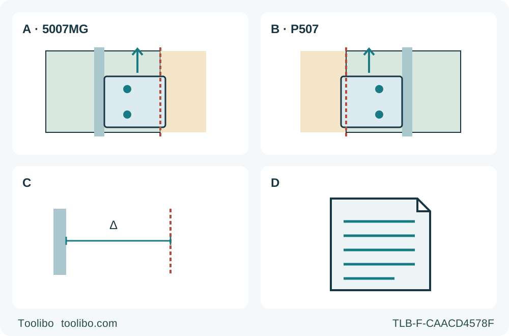
A · Normalize the MG forward frame
Use the actual operating perspective: with forward travel upward, the 5007MG blade is right and broad retained-base support left. Do not derive the plan from a mirrored underside.
B · Normalize the P507 top view
Rotate the source’s labeled top view, do not reflect it. Upward travel puts its blade left and broader retained support right; remove the battery before checking.
C · Qualify the real contact edge
Locate the actual base-to-straightedge contact and measured kerf offset; neither blade side nor the other saw’s scale supplies a universal distance.
D · Accept the entire isolated layout
Record retained/waste support, blade corridor, guide/clamps, grips, body outside the blade line and the full cord or accessory path. An unresolved point holds the cut.
A and B are stationary isolated plan views normalized to upward forward travel. Green marks retained support, pale tan marks waste, the dashed red line is the blade path, and two neutral dots identify grip contacts without placing the operator’s arms or body. MG is unplugged; P507 has its battery removed. These exact examples do not define every saw or a preferred handedness. Body position must remain outside the blade line independently of which side carries the broad base. C requires actual guide-offset qualification; D records all support and clearance checks. No powered cut or support rating is depicted.
“Blade left” and “blade right” describe the saw relative to its forward travel, not the side of a photograph where the blade happens to appear. Confusing those frames can put a guide, the supported retained piece or the operator’s body on the wrong side of a plan. It can also make a mirrored diagram look plausible until the real tool reaches the end of the cut.
This guide produces one checked, unpowered layout for an ordinary square edge-start cut. It uses two exact examples: the documented US Makita 5007MG, with the blade on the operator’s right when looking forward along travel, and the US RYOBI P507 under 990000975 REV:05, with the blade on the operator’s left. Those identities are established from their actual operating figures, including the P507’s explicitly labeled top view—not from battery type, handle shape or brand reputation.
The examples retain their original correctly qualified wood assemblies. The P507 also requires its already commissioned approved power system and complete owner documents; this article teaches no battery pairing or charging. No cutting is needed to complete the layout decision. A later sample belongs to the selected model’s complete owner workflow.
Establish a travel frame before naming a side
Physically unplug the 5007MG or remove the P507 battery before handling, measuring or rehearsing. Keep the stopped blade guarded. Place the tool in its normal upright orientation on a suitable stable surface, without exposing the underside to hands or allowing the blade to contact the surface.
Identify the front of the base, rear handle and intended forward direction from the actual instructions. Imagine looking over the rear handle toward that forward direction. Only in that frame name the blade side and the broader supporting part of the base. A front-on view reverses the page’s left and right compared with that operator frame.
When drawing a plan, put forward travel toward the top of the page. Rotate an actual top view into that direction; do not mirror it. For the P507, the source top view has forward travel toward page-left and the blade toward page-bottom. Rotating the page so forward points up puts the blade on the left. The 5007MG operating perspective resolves to a right-side blade in the same forward frame.
Do not use a bottom view of the base as though it were a top view. Looking at the underside reverses the relationship unless the view is explicitly transformed correctly. If the actual tool and source perspective cannot be reconciled, stop the drawing and resolve identity and orientation before planning a cut.
Mark the wanted piece before positioning the saw
Draw the intended cut, label the retained piece and waste, and identify their supports. The manuals require the saw to remain on supported work rather than on the piece being cut off; the 5007MG specifically places the wider base on the solidly supported portion. A comfortable view of the line does not justify moving the main bearing area onto waste that will separate.
In the normalized square-cut examples, the 5007MG’s broad supporting base lies to the left of its right-side blade, while the P507’s broader base area lies to the right of its left-side blade. The drawing therefore puts supported retained material left for the MG example and right for the P507 example. This is a useful comparison of these two actual bodies, not a rule that every piece of wood must be cut from one side of a room.
You may need to reposition the loose workpiece and rebuild its supports to obtain the required relationship. Do that while isolated and before clamping the final layout. Do not solve an inconvenient retained side by pulling the saw backward, using it upside down, crossing hands or relying on a narrow unsupported lip of base.
Support the offcut as well as the retained material so it cannot sag, twist or close the kerf. Keep all supports out of the complete blade corridor. “Retained side supported” is necessary, but it does not mean the other piece may be ignored or caught by hand as it falls.
Locate the guide from the actual contact edge
For a guided rip, identify which edge of this particular base will contact the secured straightedge. Measure and verify its relationship to the actual kerf under the same zero-bevel and blade configuration. Do not copy the other model’s guide offset or assume that a blade-left layout is a numerical mirror of a blade-right one.
The P507’s manual describes an asymmetric width scale—up to 4 inches to the right of the blade and 1 inch to the left—but those markings are not permission to assume a universal guide distance or support width. They are model-specific references, and actual blade thickness still requires a trial-cut check under its complete procedure.
On the drawing, place the guide on the supported retained side only where the real base can contact it continuously and the clamps clear the whole tool. If a clamp interferes with a guard, handle, motor housing or exit position, redraw the layout. A line on paper cannot authorize operating over a clamp or removing necessary workholding.
The blade side also does not identify a rail interface. Neither this comparison nor a flat base grants direct rail compatibility or an adapter approval. Keep this exercise to the already qualified straightedge/contact arrangement in the model’s owner scope.
Plan the body and both hands separately from base support
The broad base’s location is not a body-position instruction. Both manuals require the operator’s body to remain to either side of the blade, not in its line, and require firm two-hand control. Use the actual provided rear handle and front grip; do not invent another gripping surface because the blade is easier to see from one side.
Do not classify a saw as “for right-handed people” or “for left-handed people” from the blade location alone. The practical question is whether you can use its prescribed grips with stable footing, a clear view sufficient for the task and no reaching across or behind the blade. If not, change the work arrangement or seek an appropriate alternative; do not exchange hands in a way the actual controls and manual do not support.
Our plan-view diagrams deliberately use no directional forearms. Neutral grip markers can identify two required contacts, but they cannot prove where a person’s torso safely fits. Evaluate that with the actual isolated tool and complete manual, keeping both hands out of the underside blade zone and never using a hand to steady the work.
For the corded MG, route the cord so it cannot enter the blade corridor or snag during travel. For the P507, battery removal—not the resetting lock-off button—is isolation. The absence of a cord does not remove guide, support, guard or body-clearance obligations.
Rehearse entry, middle and exit while isolated
With the work and guide secured and power physically disconnected, assess entry, middle and exit reach and clearances beside or safely above the intended path. Keep the blade guarded and all teeth clear of the uncut stock; do not push a projecting blade into the work or force the guard open for rehearsal. Stop if these checks cannot be completed safely. Confirm that the broad base remains supported, the chosen guide contact remains available, and the required grips can be maintained throughout the intended movement.
Inspect the underside and the exit separately. A plan that clears the first half of the cut can still put a support, clamp or trailing cord in the final blade path. A long workpiece may also exceed safe reach even though the blade-side relationship is correct. Stop and change the layout if it would require leaning across the line or chasing a moving offcut.
Keep depth and bevel settings within the actual selected owner procedure. The P507’s less-than-full-tooth safety limit and maximum quarter-inch projection both apply; the MG’s own depth advice remains separate. This drawing does not establish a shared blade depth, a universal base dimension or an acceptable overhang.
Accept the layout, not a handedness slogan
Record the model and document, forward direction, blade side, broad-base bearing area, retained and waste pieces, guide contact edge, actual offset reference and isolation method. Then confirm support through separation, clamp and cord clearances, both prescribed grips and a body position outside the blade line.
If every point can be established, the result is an accepted isolated layout that can proceed to the selected model’s remaining preparation and ordinary supported sample. It is not a safety certification or permission to skip guard, blade, supply and protective-equipment checks. If a point remains uncertain, record that exact hold instead of choosing the diagram that looks more comfortable.
When a later cut is completed, release the trigger, wait for actual standstill and lower-guard coverage, and isolate before checking the result. If binding occurs, release and hold the tool motionless until it stops; never pull a moving blade backward. Correct perspective helps build the plan, but it never replaces those operating requirements.
Models referenced