
P507 identity, separate knobs and measured guidance
A shows the P507 6½ in blade, 5/8 in bore, 4,700 rpm specification and detached battery. B identifies front bevel knob F and rear depth knob D with the quarter-inch ceiling. C shows the width scale reaching one inch left and four inches right of the blade. D is a stationary upward-travel plan with blade left, broad retained base and clamped guide right, plus two neutral grip contacts.
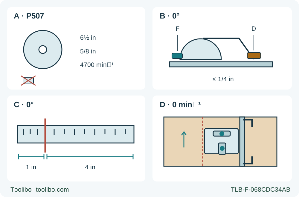
A · Match the documented owner system
Confirm the P507 body, original 6½ in / 5/8 in wood assembly and actual approved commissioned power system; keep the battery detached for setup.
B · Secure both settings
Lock bevel knob F at zero and depth knob D so projection is less than one full tooth AND no more than ¼ in.
C · Verify the real kerf
The base scale reaches 1 in left and 4 in right. Use the zero notch and a scrap trial to establish actual guide offset and retained dimension.
D · Rehearse while isolated
Keep the base on the retained supported side, clamp the guide clear of travel and reserve both hands for the original grips.
All setup and the D rehearsal occur with the battery removed. A is an existing-assembly qualification, not a fitting sequence. B shows only the numerical ceiling: the actual setting must ALSO expose less than one full tooth below the work, while never exceeding ¼ in. F and D follow the manual overview letters for bevel and depth, not a shared adjustment. C depicts the width scale limits, not a factory guide offset. D is a conceptual isolated plan, not a live cut: upward travel places this P507 blade on the left and the supported retained base on the right; the dots identify the two grips without suggesting body position.
The RYOBI P507 has its own combination of controls: a rear depth knob, a front bevel knob, an either-side lock-off button and a base width scale extending farther to the right of the blade than to the left. Learning that combination is more useful than assuming every 18 V circular saw behaves like another model. This workflow uses the documented P507 to prepare and accept an ordinary square cut in known wood with a clamped straightedge.
The source is manufacturer manual 990000975, dated 5-6-20, REV:05. Its cover, specifications and illustrations identify P507. The current US product page independently identifies the model, but does not establish that this 2020 manual is the latest supplied revision. Use this guide only when the actual tool and the owner’s complete instructions match that documented body. Keep the full manual available; this article does not replace its warnings or assembly instructions.
Qualify the already assembled saw and its power system
The documented saw is 18 V DC, with a maximum 6½ in blade, a 5/8 in arbor and a no-load speed of 4,700 rpm. Its listed cutting depths are 2 1/16 in at zero and 1 7/16 in at 45 degrees. Those are model specifications, not permission to install any blade of roughly the same diameter or to expose the whole blade below thin wood.
Start with the original suitable wood-cutting blade and its correct inner washer, outer washer and screw already properly installed. The outer washer must engage the spindle flats; an excessively thick blade can prevent proper engagement and fastening. A damaged, unidentified or questionably assembled blade system stops the task. Obtain the complete matched instructions or qualified correction instead of reconstructing a fitting procedure from a diagram.
One model-specific distinction matters when assessing the documentation: this manual specifies clockwise screw removal and counterclockwise tightening. Do not transfer a conventional right-hand-thread rule from another saw. The manual also includes oil on the washer-to-blade contact surfaces; a generic instruction to make every flange interface dry would contradict it. These are assembly-qualification boundaries, not directions to loosen the existing screw, add oil to an assembled blade or perform a partial blade change. No torque is invented here, and the spindle lock is never used to stop a moving blade.
The owner must have an already commissioned genuine battery and charger combination expressly allowed by the actual tool/appliance/battery/charger correlation supplement 987000-432, plus the complete instructions for that pair. A matching voltage label or a retailer’s suggested accessory is not enough. This article does not name a new pack pairing, teach charging or promise kit contents. If the supplement or the actual pair’s approval cannot be established, do not fit a pack and proceed.
Use only an undamaged, ready pack maintained and charged under those instructions. The P507 manual prohibits using, storing or charging the product or batteries below 50 °F or above 100 °F, and prohibits damp charging locations. Do not replace those limits with another model’s temperature range. Keep detached terminals away from metal objects and do not use a pack or charger that has been dropped or received a sharp blow.
Isolate and inspect before adjusting anything
Release the trigger, let the lock-off reset and remove the battery by operating its side latches. Keep the battery out during assembly checks, adjustments, cleaning and when the saw is not in use. The lock-off reduces accidental starting but does not make an installed battery harmless. Do not carry the saw with a finger on the trigger.
Inspect the lower guard before each use. It must move freely and close immediately, and its spring must work correctly. Before each use, with the battery removed, also check free guard movement without contact against the blade or other parts at all angles and depths of cut. After a drop, check the guard and bumper through all depth settings, and verify that the guard does not contact the blade or another component at all angles and depths of cut. A bent guard, sluggish return, damaged spring or switch fault is a service condition. Never tie the guard open. In this ordinary edge-start cut it operates automatically; the pocket-cut section of the manual is not part of this workflow.
Check that the base is sound, the handles are secure and the blade is sharp, clean and undamaged. The tool is for wood products, not abrasive wheels or nonwood cutting blades. Choose flat, dry, untreated stock without nails, knots or hidden foreign objects. Do not use warped or wet lumber as a convenient practice piece. Unknown coatings and contamination require a different risk assessment, not more feed pressure.
Wear eye protection with side shields marked ANSI Z87.1. Arrange appropriate dust protection and ventilation; the manual calls for a face or dust mask when the work is dusty and hearing protection during extended operation. Prepare hearing protection for the work rather than treating a short test as a reason to ignore noise. This documented body does not establish an external extraction-port setup, so do not invent an adapter or attach a hose where the manual shows none.
Set zero bevel and satisfy both depth limits
With the pack removed, identify the front bevel adjustment knob and the rear depth lock knob. The overview labels them F and D respectively. They do different jobs and must both be secure before cutting. The bevel range extends from zero to 50 degrees, but this sample uses zero only. Loosen the bevel knob, bring the base and motor housing to the zero setting, then tighten securely.
Verify the square relationship of blade plate and base with a carpenter’s square, following the manual’s isolated checking position and avoiding the teeth. The factory zero stop is not a guarantee after damage or wear. If the check fails, stop for the complete documented adjustment or qualified service; do not try to solve it by forcing the base against a guide during the cut. This article does not teach the separate stop-screw adjustment.
Set depth for the actual scrap thickness. Loosen the rear depth knob, keep the base flat against the work and raise or lower the saw, using the scale on the back of the upper guard as a reference. Tighten the knob securely and verify that the setting holds.
There are two relevant limits in the same manual: the safety section requires less than one full tooth visible below the work, while the operating section and Figure 6 set a maximum of ¼ in below the material. Apply both. The ¼ in figure is a ceiling, not a target that overrides the tooth rule. Select a setting that cuts through while leaving less than a full tooth exposed and no more than ¼ in below the work. If the installed blade or work thickness makes that relationship uncertain, resolve it before energizing the saw.
Build the guide around the actual kerf
Mark the retained dimension and waste side. Place the wood on a stable platform and clamp it so it cannot move. Keep supports out of the blade path, near the cut, with adequate support on both sides of a large panel near the line and outer edges. The saw’s base must rest on the supported retained portion, not the piece being cut off. Plan for the final separation so the offcut cannot close the kerf or pull the blade sideways.
Clamp a straightedge firmly to the work, as in Figure 15. Use a straightedge for the long rip in this exercise; the manual calls for a guide when ripping. Check the guide’s actual straightness and the clamps’ security. Leave clearance for the motor housing, base and guard over the full travel. No hand is assigned to steady the board: the manual shows that as an incorrect operating method.
For a square cut, start from the base’s 0° blade-guide notch, not the 45° notch. Blade thickness varies, so establish the actual notch-to-kerf and base-edge-to-kerf relationship with a scrap trial. Position the guide to preserve the intended retained dimension. Do not slide the guide against the teeth and call that a verified offset; the result must be checked after an actual controlled sample.
The base width scale measures up to 4 in to the blade’s right and 1 in to its left. It is a measurement aid, not a universal straightedge offset or a substitute for checking the retained dimension. Read its sides relative to the saw’s forward direction. The manual’s Figure 14 is an explicit top view: the blade is on the operator’s left when following forward travel. A conceptual upward-feed plan therefore has the cut left and broad supported base to the right.
With the battery still removed, rehearse from entry through exit. Both hands must reach the original grips without shifting near the blade. Stand to the side of the blade line, keep stable footing and make sure the guide, clamps and supports do not cause the base to rock. If the last part of the cut would leave the saw unsupported or require catching the waste, redesign the setup now.
Cut, stop and assess before the next workpiece
Once all conditions are met, keep the trigger released and install the qualified ready pack. Confirm that both side latches have snapped into place and the pack is secure. Put the front of the base on the supported work with the blade clear of the edge. Hold the saw firmly with both hands. Press the lock-off from either side, then pull the trigger, and let the blade reach full speed before entering the wood.
Guide the saw steadily against the straightedge without forcing it or twisting sideways. If it stalls or binds, release the trigger immediately and hold the saw motionless until the blade has completely stopped. Never pull a rotating blade backward from the kerf. Remove the pack before correcting support, alignment or obstruction. Do not turn a difficult sample into repeated restart attempts.
For normal completion, retain control and support, release the trigger and wait for complete standstill before withdrawing or lifting the saw. Confirm that the lower guard has closed before setting it down. The lock-off resets each time the trigger is released, but that is not a brake claim or a replacement for waiting. Remove the battery before measuring or changing the guide.
Check retained width at several points, squareness of the cut face and whether the edge is straight. Look for burns, tearing, an irregular kerf or signs that the guide moved. Also assess the process: a correctly sized piece does not pass if the stock rocked, the base lost support or the blade bound. Correct the cause while isolated and repeat on scrap before cutting the intended part.
After use, clean accessible dirt with suitable clean cloths and keep the guard free of debris. Do not expose plastic parts to solvents, gasoline, brake fluid, petroleum products or penetrating oils. The manual’s blade-cleaning suggestions do not establish a complete chemical-cleaning procedure here; a fouled blade requiring removal belongs with the complete matched maintenance instructions. Store the saw with the battery removed and the pack protected under its own instructions. The completed outcome is a repeatable, stable square-cut setup for this documented P507, not approval for another blade, power pair or cutting mode.
Models referenced