
Secure the shank before mapping the route
A conceptual chuck grips straight shank before the flutes; a separate cabinet sketch includes bit projection, body, dashed battery and exit arrow.
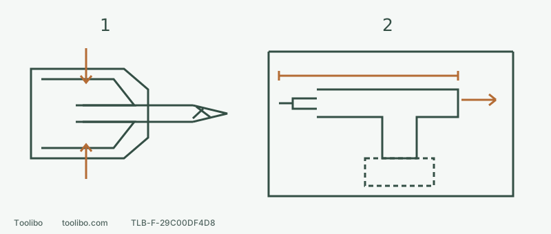
1 · Straight and hand-tight
Follow the chuck arrows with the battery removed; do not grip cutting flutes or power the chuck while holding it.
2 · Complete path, not bare-body length
Measure entry, feed, battery and hand clearance, then reserve an external isolated changing place.
Conceptual sections, not chuck disassembly or a fit guarantee. Battery outline is a separately measured template while the tool is disconnected.
Identify the model and check for danger first
Observe from a safe distance. If the battery is smoking, leaking, swollen or unusually hot, do not approach or handle it to read a label or remove it; stop using the equipment and contact the manufacturer. Without those signs, confirm FX1131 rather than FX1231. Hammer functions in their shared manual belong to the latter.
For normal equipment, release the trigger, wait for a complete stop, centre-lock the direction selector and remove the battery. Keep power disconnected for accessory installation, measurement and control adjustment. Check the bit is clean and its shank is neither bent nor damaged. Do not install a damaged shank for a trial.
Complete the hand-tightening procedure
- Follow the chuck’s UNLOCK/LOCK arrows. Turn the sleeve by hand towards UNLOCK until the jaws accept the shank. Never hold the chuck while pulling the trigger to open or tighten it.
- Insert the clean bit straight along the chuck axis. For a small bit, insert up to the flutes with the jaws on suitable shank; for a large bit, follow this model’s instruction to insert as far as it will go. Do not insert it at an angle or grip only a short end for clearance.
- Turn towards LOCK and tighten securely by hand. Check that the bit is centred and the jaws grip suitable shank rather than cutting flutes. Confirm manually that the accessory is not loose. If uncertain, open and refit it; powered rotation does not replace inspection.
This is the FX1131 hand-tightening method, not another model’s counted-click rule. Removal also starts with a full stop and battery removal. Allow a hot bit to become safe to handle before opening towards UNLOCK.
Draw the whole assembly from the hole axis
Draw the hole axis and measure back from the correctly installed bit tip to the tool’s rear. Add the handle and hand position. Keep the battery separate: measure its undamaged case and add its envelope to side and top views using the real mounting-plane reference. Do not bridge contacts with a metal ruler or put a cardboard template into the connector.
Include cabinet panels, clamps and the entry opening. Suppose the real tip-to-tail assembly measures 255 mm but the straight working space is 240 mm: reject that alignment. These are hypothetical measuring examples, not fixed FX1131 dimensions. The published 5.9-inch body length cannot replace this measurement.
Mark the end of feed and the withdrawal position too. The battery, wrist and rear must clear obstacles throughout. Provide a stable external place to remove the battery and change to a driver. Fitting at the starting position alone is not a pass.
Select range and clutch deliberately
The top selector’s 1 position gives lower speed and higher torque. The manual uses it for suitable screw-driving, larger-hole and metal or plastic work among its examples. Position 2 gives higher speed and lower torque for suitable lighter drilling. Accessory and material requirements still apply; these examples are not unlimited diameter permission. Shift only at a complete stop and engage fully.
The collar has numbered positions 1–18 and a drilling position. For ordinary screws, begin in range 1 with a low clutch setting on matching scrap. Drilling locks the clutch for drilling; it is not a workaround for a troublesome screw. Trigger pressure changes speed within the selected range.
Define a successful trial
Clamp the trial material and remove rulers and templates. With your finger off the trigger, install and latch the specified battery, then release the centre lock and select the appropriate direction. Seat the matching driver in the screw and start smoothly with a secure grip. Record the combination only when the screw reaches its required position without head or material damage.
If the clutch releases early, stop and disconnect, check the pilot hole and bit, then make a small adjustment and repeat the same battery-restoration and direction sequence. Slipping, body contact, trapped trigger access, stalling or unusual heat or smell calls for stopping, not more pressure. Move into the confined position only when secure engagement, the result and the whole route all work.
Models referenced