
Check contact before adding torque
Top views contrast a fitting tip, an undersized tip and a damaged recess.
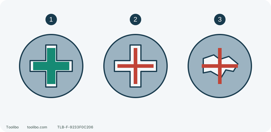
1. Matching contact
Correct type and size seat normally along the screw axis.
2. Too small
Apparent insertion is not reliable engagement.
3. Damaged recess
Replace the damaged fastener rather than grinding it with more pressure.
Conceptual fit, not a brand-specific drive profile or dimension. Match the fastener type and size; perform this check with power isolated.
Check whether the bit really engages
This is an ordinary screwdriving check for stable equipment safe to approach. Smoke, leakage or developing abnormal heat instead means keep away, not approach to remove the pack. Otherwise, release when the bit jumps or the screw stops advancing, wait for standstill and remove the battery before inspection.
Remove the bit and match the fastener’s drive type and size identification with a sound driver. Similar-looking crosses or apparent insertion do not establish matching contact. While isolated, align the bit with the screw axis and check normal seating, obvious rocking or edge-only contact. Coating, debris or a damaged recess can obstruct fit; do not reshape the screw head to suit the wrong bit.
Replace a rounded/chipped bit or damaged fastener before continuing. More axial pressure while slipping is not the remedy. Never hold a rotating screw or hold the work with one hand while drilling with the other; restrain the work independently.
Identify where motion is lost
Use the event already observed, without running it again. Keep isolated for retention checks: use an allowed bit/holder with the chuck correctly gripping its intended shank, not an unsuitable transition.
Swipe or scroll horizontally to see all columns.
| Observed event | Check first | Do not |
|---|---|---|
| Bit jumps or rubs in recess | Drive type, size, wear and alignment | Grind the recess with more pressure |
| Bit moves relative to chuck | Shank seating and chuck condition | Pack gaps with paper or tape |
| Bit stays engaged with repeated clutch release | Clutch setting and joint resistance | Force it in drilling mode |
| Motor stops or housing twists | Stall, overload or binding cause | Pulse repeatedly hoping to break through |
If the row is unclear, remain at external inspection. Sound alone does not diagnose a failed gear.
Check direction and mode
Use this model’s direction markings; do not transfer another brand’s left/right switch positions. Wait for full standstill before direction, mechanical gear or mode changes. Ordinary right-hand screws drive opposite their removal direction, but special fasteners follow their own requirements.
Use the appropriate screwdriving setup for ordinary nonstructural work. Numbered clutch positions are relative settings, not newton-metres. The same number on another drill or material does not imply the same result. Drilling or hammer mode is not a valid starting point for checking screwdriving clutch behaviour.
Establish a setting on representative scrap
This applies only to ordinary nonstructural assembly without a specified installation torque. Match material, thickness, support and sound screw specification. If a pilot hole is required, use the fastener manufacturer’s material-specific instructions, not a universal percentage.
- Isolated, fit the matching bit, choose a conservative clutch setting, restrain the sample and align the screw.
- Keep your finger off the trigger before installing and securing the compatible battery; start normally at low speed.
- Stop to inspect. A proud head with intact material may justify a small setting increase after isolating again. Repeat step 2 preparation after every adjustment.
- Stop increasing once the joint’s required seating is reached without damage. Excess depth, damaged recess or cracking means stop and review the plan, not demand more output.
If the sample fails, do not return directly to the finished work. Do not bypass the clutch using drilling mode.
Sudden resistance calls for a joint review
A screw that initially advances normally then stops calls for checking length, material, alignment and pilot-hole requirements. Unknown resistance inside a wall is not investigated with more force; identify the target and work conditions first.
Structural joints, specified torque or special installation requirements need their approved procedure and equipment, not a scrap-test clutch number. If accessory, direction, setup and task are suitable but the tool remains abnormal, stop and arrange inspection. Report the slipping interface, screw/material specification and sample result rather than only “no power.”