
Back the exit face
A vertical bit enters clamped wood and its backing, with open clearance above the bench.
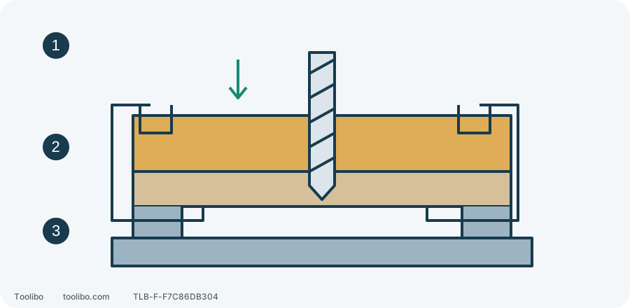
1. Axial feed
Start with the tip located; reduce feed near breakthrough.
2. Tight backing
Clamp stock and sacrificial backing together.
3. Safe clearance
Support securely without putting the bench in the drilling path.
Section diagram, not dimensions. Keep the backing tight against the exit face; the hole path must not reach the bench or a hand.
Start with a sample whose two faces are accessible
This exercise is a through-hole in known ordinary wood free of nails and screws, not a wall, floor, structural joint or reclaimed material with unknown coatings. Match the finished work’s material and thickness. Hole size must be within tool and bit limits. One sample hole exposes problems before they are repeated on the finished piece.
Use a straight sharp undamaged bit suitable for wood. Ordinary twist bits can drill wood; pointed woodworking cutters have their own requirements. This exercise uses a normal twist bit and close-fitting backing, not hammer mode, sideways enlargement or reverse-face completion.
Plan the centre and exit together
Mark the centre with crossed lines rather than a broad dot. Check project-specific edge distances, nearby holes and defects; there is no universal spacing here. Inspect underneath so the tip and emerging accessory cannot hit clamps, bench, hands or other objects.
With the battery removed, fit the bit, choose rotary drilling and set the range required by tool and accessory. Place clean flat sacrificial wood against the back. Remove chips between layers and cover the area around the exit, not merely a tiny point below the tip.
Clamp work, backing and stable support as a restrained assembly. Keep clamps outside the bit path while holding the layers together near the hole. Still isolated, gently check for sliding, pivoting or lifted backing. Do not support it by hand. Plan clearance beneath too; a sacrificial board does not authorize drilling the bench.
Start on the mark without steering sideways
- Fit suitable eye protection, arrange wood-dust control and secure loose sleeves and hair. Keep hands from beneath the hole and check restraint before starting.
- Keep your finger off the trigger while installing and securing the compatible pack. Put the tip on the crossed marks, hold the intended axis and start slowly, not at high speed before contact.
- Once cutting is established, adjust speed within tool and bit instructions and maintain steady axial feed. The edge must cut rather than rub. Release at marked speed loss or twisting instead of adding pressure.
- Clear flutes using the tool’s normal withdrawal procedure without reaching into moving flutes. Stop, isolate and let the bit become safe before clearing attached debris with an appropriate tool.
If the tip wanders, stop and review mark, point and axis. Do not push sideways inside the hole to drag it back into position; that alters shape and can increase binding.
Ease feed near breakthrough
Plan depth and available travel from board thickness before starting rather than reacting to a sudden plunge. Reduce pressure near the back so the cutter enters the closely fitted sacrificial backing instead of pushing out the last fibres. End at the planned through-depth, not by continuing toward the bench.
Binding, moving work or separated backing means release, wait and isolate safely. No repeated trigger pulses or clamp release while rotating. Finishing from the opposite face requires separate accurate relocation and is not part of this exercise. Backing never replaces exit inspection.
Inspect three first-hole results
Swipe or scroll horizontally to see all columns.
| Observation | Interpretation | Before the next hole |
|---|---|---|
| Entry misses the centre | Mark, point or axis needs attention | Remark the sample and check a suitable sharp bit and slow contact start |
| Entry acceptable but exit splintered | Exit support or final feed needs attention | Check backing gaps and ease breakthrough pressure |
| Burned wall, poor chip removal or vibration | Accessory, chip removal or load may be unsuitable | Stop and isolate; do not simply raise speed or pressure |
Release clamps only stopped and isolated. Clean, then inspect both faces and the wall. Repeat the setup only when location, exit and diameter meet the project’s needs. Verify corrections on scrap rather than treating breakthrough alone as acceptance.