
Identify the holding interface before fitting
End views show round and hexagonal shanks; schematic side views contrast smaller SDS-plus and larger SDS-max connections.
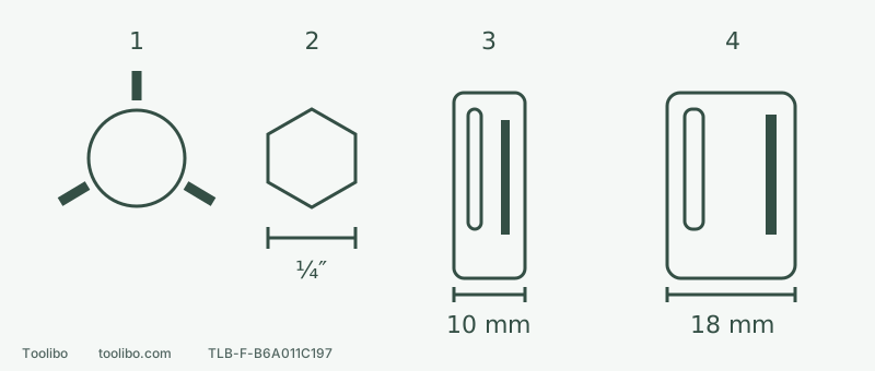
1 · Round shank
Three suitable jaws grip the designated shank within their size range.
2 · Hex shank
Across-flat size alone is insufficient: quick-change retention and impact rating must also match.
3 / 4 · SDS-plus / SDS-max
Different connection sizes and structures; confirm the complete system name and prescribed retention check.
Grooves are conceptual, not a count or machining template. The 10/18 mm values describe connection diameters, not hole limits.
Inspect the back end, not just the tip
Place the uninstalled accessory securely and look at its holding section. A cylinder, six flats, longitudinal grooves or retention recesses describe the connection, not the cutting material. Stop and remove the tool battery as instructed before inspection; no running is needed.
Do not trial-fit bent, cracked or badly worn shanks. Identify an unknown old accessory from its exact model and manufacturer information rather than forcing it into a holder.
Pair each shank with its holding method
Swipe or scroll horizontally to see all columns.
| Appearance | Holding principle | Further checks |
|---|---|---|
| Cylindrical shank | Suitable three-jaw chuck grips the designated section | Diameter within range; jaws on shank rather than cutting flutes |
| Common 1/4-inch hex quick-change shank | Flats transmit rotation; matching retention prevents withdrawal | Across-flat size, groove position and holder requirements, not hex shape alone |
| Grooved SDS shank | Matching SDS holder uses the connection geometry for drive and retention | Exact SDS-plus or SDS-max identification, dimensions, instructions and retention check |
Cutting diameter and round-shank diameter can differ. A reduced shank does not increase the drill’s permitted cutting capacity. Hex shape is not an impact rating or permission for axial hammering.
Distinguish SDS-plus from SDS-max
The connection ends differ in size and shape: SDS-plus has a 10 mm connection diameter and SDS-max 18 mm. These are interface dimensions, not a requirement that every hole be 10 or 18 mm. Read the complete system name on package and tool, using dimensions and appearance as supporting checks.
Not all grooves are equivalent. Counting one groove does not establish compatibility, and clamping an SDS shank in an ordinary three-jaw chuck is not the correct holding method. Follow the matching tool’s insertion, retention and removal instructions.
Nor does every rotary hammer accept every SDS type. Other interfaces exist, and plus/max do not directly interchange. Dedicated adapters exist, but this identification guide does not authorize arbitrary combinations. Exact adapter, tool, accessory and permitted mode need separate approval.
Complete a round-shank example
British Bosch PRO Wood Brad Point 2608577711 is listed for wood, with a cylindrical shank and cutting/shank diameters both 8 mm. The GSR 12V-35 in manual 1 609 92A 9UK, November 2024, has a 0.8–10 mm three-jaw chuck range and 32 mm wood capacity. Ordinary wood holes use drilling mode.
The connection check passes because the 8 mm round shank fits the holding range, the wood use matches and the 8 mm hole is within the dimensional limit. Actual condition, installation space, workholding and operating conditions still need checking. This is not the GSR 12V-35 HX with its different holder, or an automatic approval for similarly named US tools.
If you only have a 1/4-inch hex quick-change driver, this 8 mm round-shank bit cannot be inserted directly by that method. Choose an approved tool/accessory arrangement instead of treating hole capacity as holder compatibility.
Check the fitted result without forcing it
- With the battery removed, compare accessory code, shank markings and holder instructions; match both interface and action.
- Install and lock as that holder requires. Do not tighten by holding the chuck under power, hammer the shank in or grind it to fit.
- Perform the prescribed retention check. Failure to lock, abnormal release or incorrect jaw position means stop, not run it to see whether it settles.
- Confirm material, hole size, accessory condition and mode before ordinary work. Stop and isolate for wobble or abnormal sound.
Record four separate results: inserts correctly, retains reliably, permits the action, and suits the material/size. All four must pass; an unanswered item cannot be supplied by similar appearance.