
Rear-to-front retention, then the supplied punch plate
A sheet wraps around a rectangular pad between rear 5A/5B and front 6A/6B; a second view shows installed paper above the punch plate.
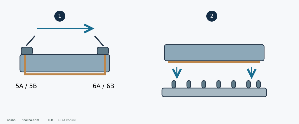
1. Rear first, front second
Unplug. Capture the rear end under 5B and lock 5A; draw paper flat around the pad, capture under 6B and lock 6A. Both ends must remain secure.
2. Align, press, remove and inspect
With fitted paper and no power, align the base to its plate and press to pierce the sheet. Remove the plate and confirm paper/pad holes match without tears or slipping.
Conceptual side sections, not exact lever geometry or a drill template. Pin count/spacing is symbolic: use only the actual supplied pattern, then remove the plate.
Confirm this machine and paper system
This is for Bosch GSS20-40, manual 2610051953 revision 08/18, not every quarter-sheet sander. Regular paper uses clamps; PSA uses its adhesive. Check retention and cut size as well as grit.
Regular paper is 4½×5½ in, approximately 114.3×139.7 mm. PSA is 4½×4½ in, approximately 114.3×114.3 mm. Converted decimals are not added tolerances. Regular paper needs extra length for both clamped ends; do not cut only the pad footprint and force it to reach.
Pad dimensions differ between this manual and product page, so do not average them into a template. Use the stated separate abrasive dimensions and stop if actual pad/paper identity is uncertain. Folded spacers or extra glue do not correct a mismatch.
First: unplug and identify front/rear clamps
For normal stable equipment, switch off, wait for all motion to stop and unplug. Inspect cord, pad, levers and retaining brackets for damage or distortion. Damaged clamps do not qualify for a powered retention test.
The manual identifies rear lever 5A/bracket 5B and front lever 6A/bracket 6B. Use the machine illustration, not left/right after turning it over. Distinguish the moving lever from the bracket that captures paper.
Unlock both levers and swivel down, remove old paper, brush accessible pad debris and inspect the contact face. No wire inside housing holes or internal blockage investigation. Replace torn, contaminated or poorly cut new paper before fitting.
Second: rear first, then taut front
- Insert one paper end beneath rear bracket 5B, keeping width square to the pad.
- Confirm sufficient length for both ends, return rear lever 5A to its starting position and lock. A tiny captured corner is insufficient.
- Wrap evenly around the pad, drawing flat rather than stretching. Check folds, bulges and unequal side overhang.
- Place the front end beneath 6B, return 6A and lock. Both ends must retain securely with neither lever half open.
A short final end means recheck size and routing. Tearing means inspect paper, folds and clamps, not pull harder. Correct paper that still slips requires mechanism assessment. Do not glue regular paper as a rescue; approved PSA is a separate option, not a repair for broken clamps.
Third: punch after fitting
Still unplugged, align the fitted sander base with its supplied punch plate and press down until the plate pierces the paper. Remove the plate afterward. It is not left attached during operation or used as a workpiece.
Check each paper opening against the pad’s extraction holes and inspect for substantial tearing or sheet movement. Do not substitute another machine’s punch pattern or drill the backing pad. Misalignment calls for checking slipped paper, orientation and accessory identity, not adding random holes.
Prepunched paper also needs inspection; “quarter sheet” does not guarantee its pattern. Punching opens the correctly installed paper’s dust path, not changes the pad structure.
Final acceptance: five checks while isolated
Confirm both ends captured, both levers locked, flat evenly tensioned paper, no tears or dangerous loose edges, and correct holes with punch plate removed. Refit required original collection equipment. Every grit change repeats these checks; the previous sheet’s success does not transfer.
PSA has separate dimensions and removal cautions. Do not import a powered adhesive-softening routine into this unplugged clamping lesson.
Printed pages 10 and 11 conflict about contact position at startup. This page does not choose between them. Until applicable start/stop instructions are clarified, do not power-trial the tool. The completed task is secure paper, correct holes and isolated acceptance, not full operating clearance.
Models referenced