
Isolate, identify original hardware, secure and inspect
A shows an isolated battery and document gate. B separates the original plain washer, screw and key as inventory, not a guessed exploded stack. C shows neutral uncounted blade engagement and a separate key-away verification cue. D is a plan-view retained clamp, independent waste support and clear straight cutting corridor.
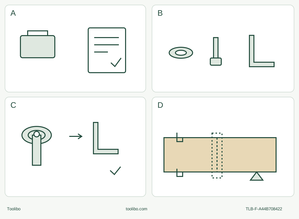
A · Isolate the exact owner system
Match actual OS593001/01-21 and commissioned power instructions; OFF/full stop/front release and pack out before adjustment.
B · Retain original parts
Identify the original screw, plain washer and provided key. Cool and remove the old blade while isolated; the parts sheet is inventory only.
C · Seat, tighten and remove the key
Clean threads/shaft, align all grooves/ribs, hold the blade with a gloved hand and tighten original screw WITH washer. Verify secure seating, then key away before power.
D · Complete and accept
Qualify actual grip/PPE/dust and all support/clearances. Full selected speed before contact; full stop before withdrawal, battery out and cooled both-face acceptance.
Original schematic, not scale or full assembly geometry. B does not prescribe a thread direction, torque or interchangeable part. C requires the original screw WITH washer tightened by the supplied key, secure isolated seating and key removal. D adds no grip or extraction hardware and does not guarantee cutting depth.
Keep the screw, washer and document together
The OS593001 in this guide is an existing US tool matched to its 01/21 owner manual, actual slide controls and original screw-and-washer holder. SKIL’s current owner-support card links that manual and a separate parts sheet; it does not provide a current product-sale link. This is not a claim that the tool is currently sold, discontinued, or equipped with a particular motor technology. The OS593002 text in shared filenames is not another physical model counted here.
The project is a complete short straight separating cut in known, new, dry, untreated and uncoated loose softwood. It ends with both-face inspection after the tool has stopped and the battery is removed. It does not authorize installed-wall work, hidden services, a free interior plug, or cutting unidentified reclaimed material.
Identify the actual original recommended SKIL bi-metal plunge-cut blade. The matched manual’s page 19 table explicitly supports wood for that blade. Do not select an aftermarket blade by silhouette alone, borrow another SKIL interface, or invent a blade SKU, numerical accessory rating or cutting-depth capacity. Actual original identity, manufacturer limits, sharp undamaged condition and sufficient installed reach must all be established before the sample is eligible.
Separate identity evidence from repair instructions
The linked Version A parts sheet is dated 2018/11/15 and identifies OS593001 body 0860168001. It lists a plain washer 5650017009, hexagon socket screw 5620340002 and hexagon wrench 5680028002, one of each. Those are original-inventory and identification facts, not a new assembly recipe, torque specification or assurance that every physical revision accepts a replacement part. Unknown, missing or substituted hardware requires manufacturer confirmation before use.
The operating manual supplies the actual change sequence. A visible hex socket does not authorize a guessed key size or thread direction. Keep the actual original screw and washer together, use the provided key, and retain the correct supplied document. Do not add a conical washer, rod, lever, adapter or extra clamp part from another tool.
Establish power and isolated condition first
Use only the actual already-commissioned original BY519701 battery and SC535801 charger selected for this project, with their complete matching instructions. Both appear in the tool’s page 11 approved list. That list is not a charging tutorial or approval of every pack with a similar voltage label. If identity, prior damage, operating conditions or the independent power instructions are unresolved, stop rather than create a new pairing.
The specification table says 20 V DC, while the illustrated body bears 20V MAX. This guide retains that wording distinction without inventing a nominal-voltage conversion. The documented working range is 14–104 °F (−10–40 °C), and storage is 32–104 °F (0–40 °C); these are not charger temperature limits. Follow each actual component’s instructions. Keep fluids out, protect detached terminals from metal objects, and do not use modified or damaged power items. Battery service belongs to the manufacturer or authorized provider, not this project.
Slide the switch backward to OFF and wait for full standstill. Press the battery-release button on the front of the pack and slide it completely out. Keep it out for all mounting, cleaning and adjustments. Inspect the housing, designated soft grip, switch, drive shaft, accessible original hardware, screw, washer and blade. Cracks, missing parts, looseness, damaged threads, binding, unreliable controls or unexplained condition are a qualified-service hold. Do not insert the battery to test a doubtful holder.
Mount through the native key route
Let an old accessory cool. Wear protective gloves for the sharp blade and keep your fingers away from the cutting edge. The blade must be sharp and free from bending, cracks, breakage or suspected damage. With the tool OFF and the battery removed:
- Use the provided hex key to loosen the original clamping screw with its washer. Remove the old accessory before seating a replacement; do not stack blades.
- Make sure the internal threads and drive shaft are clean. If debris, damaged engagement or an uncertain original part cannot be resolved within the documented external procedure, stop.
- Position the original bi-metal blade on the drive shaft so all accessory grooves align with the shaft ribs. Choose a forward-facing direction that keeps the whole moving tool and blade clear. The documented 30° indexing does not permit backward-facing plunge blades.
- Hold the blade with a gloved hand, away from its sharp edge, put the original clamping screw with its washer back into the tool and tighten using the provided hex key, as Figure 6b shows.
- Verify correct secure seating while still isolated. Remove the hex key and clear loose tools before any later battery insertion. If the blade moves, the screw cannot secure normally or the original engagement remains uncertain, hold for correction—never use a powered seating test.
No tightening torque, key dimension, turn count or thread-direction instruction has been invented here. The flat washer’s identity does not justify replacing it with an apparently similar hardware-store part.
Arrange a sample that can be cut and inspected
Work in a clean, well-lit, dry, non-explosive area with stable footing and bystanders excluded. Do not work tired or impaired. Check both wood faces and the full route for nails, screws, staples, embedded objects and material uncertainty. Keep loose clothing and hair away from moving parts. Painted, treated, composite, contaminated and unidentified stock are outside this clean-wood task.
Mark the intended line on both faces, clamp the retained piece securely to a stable support and independently support the waste. Separation must not cause the waste to fall uncontrollably, close the kerf or tear off the final fibers. Do not rigidly trap both sides. Confirm that the actual blade reaches through without the holder or body contacting the work, and clear the entire oscillation, underside, exit and permissible rear-tool movement envelope of clamps, supports, hoses and body parts.
Use the actual soft-grip barrel hold documented in the controls and application figures. Keep the free hand away from the cutting range and underside; it must not support the wood. Do not grip the battery, head or hot ventilation openings, and do not invent an auxiliary handle. If the grip, clamping and clearance cannot coexist, redesign the fixture or stop. Both faces must remain accessible for isolated acceptance.
Wear ANSI Z87.1 eye protection with side shields, full-face protection when needed, appropriate hearing protection and protective gloves during the cut. Provide dust respiratory protection and ventilation appropriate to the actual wood hazard, protective clothing and skin-cleaning precautions. When extraction devices are provided, correctly connect and use them. Isolate both tool and extractor under their own instructions before connections; the qualified equipment must be running and checked before cutting. No native hood, hose fitting or numerical suction requirement is established by this manual. Required dust controls that cannot be delivered by an approved documented system are a stop condition, not permission to rely on a nearby loose hose or a small-sample exemption.
Select speed without adding an automatic mode
The manual specifies 11,000–16,000 oscillations per minute, not rotary spindle RPM. Dial 1 is slowest and 6 fastest, with no published intermediate rate table. Page 16 uses a medium-to-high range for initial plunge. Page 12 calls for a trial on scrap to find the suitable setting. Use an equally supported and dust-qualified piece of the same material; do not turn that qualitative instruction into an invented universal dial number.
For this project, make adjustments with the switch OFF, the tool fully stopped and the battery removed. This is a conservative chosen workflow, not a claim that the manual forbids its separately described controlled no-load adjustment. Do not change speed with the blade in the material. There is no established AutoSensing, rod-lock or trigger-lock mode on this body.
After the isolated checks, keep the switch OFF, align the original pack’s rib with the tool groove and slide it fully in until the latches engage correctly. Establish the actual grip with the blade clear. Push the switch forward to ON and reach the full selected speed before touching the wood.
Complete the cut, then withdraw after full stop
Follow the marked line with controlled pressure; do not force the plunge. The source permits slow sideways movement of the back of the tool with the teeth kept in the work surface. That movement requires the already-cleared full envelope; it is not twisting a trapped blade or steering a curved cut. Use the actual blade scale only within its verified installed reach and known stock geometry, not as proof of what lies behind a surface.
After full separation, pull the slide switch backward to OFF. Wait for complete standstill before removing the tool from the workpiece, as page 16 expressly requires. Withdraw along the clear path, set down safely and remove the battery before handling the offcut or checking the blade. A bridge of uncut wood is not permission to pry or snap it by hand.
Stop and isolate for blade movement, unusual vibration or noise, loss of control, support shift, binding or overheating. The head LED follows the ON/OFF switch; rapid flashing indicates overload/overtemperature protection. It is not proof of standstill or safe mounting. The troubleshooting table’s “trigger” wording conflicts with the actual slide switch: use the documented slide OFF, not an invented trigger release. No slow-flash low-battery meaning, timed reset, repeated fault reproduction or powered cooling test is supplied here. Persistent or unexplained conditions require authorized service.
Decide whether the finished piece is acceptable
Let hot blade and material cool; avoid sharp edges. With the battery removed, inspect both faces for the intended line and size, complete separation, and absence of uncontrolled tear-out, scorch or fixture movement. A wrong-size or partly connected result is not accepted merely because the tool ran. Correct an identified blade/material/fixture issue before another sample; unresolved behavior remains a service hold. This article supplies no numerical tolerance or performance guarantee.
Keep accessible vents and switch areas clean without pushing pointed objects through openings. Avoid the plastic-damaging solvents and cleaners listed in the manual. Internal maintenance, damaged control replacement and parts substitution are not user procedures here. Store the isolated tool indoors away from children and corrosive agents, retaining the exact manual and original-parts identity.
What the evidence establishes
The current US owner card establishes a support link to the dated 01/21 OS593001 manual, not a current sales page. The operating source is complete English 1–21: power 11, controls 12–13, screw/washer attachment 13–14, plunge 16, material table 19 and care/diagnostics 20. The separate two-page 2018 parts sheet supplies identity and original inventory only. Sanding, scraping, metal, grout, charging, kit quantities and other-model mechanisms are not silently added to this complete wood-cut outcome.
Models referenced