
Three holders, three isolated checks
Three panels compare GOP18V-34 snap engagement, Milwaukee 2526-20 threaded accessory bolt, and Metabo Q SL spring pin with its clockwise 90-degree insertion turn. Inspection symbols replace blanket approval marks.
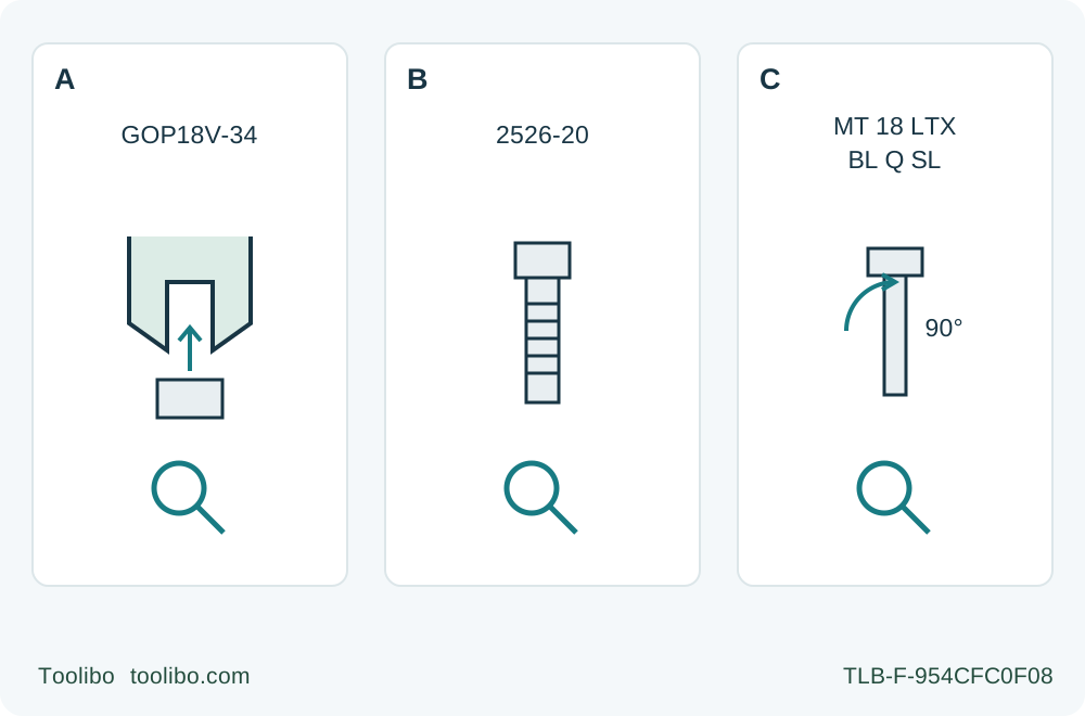
A · Identify snap engagement
Use the exact approved Bosch accessory and clean mating surfaces; press to snap without opening the release lever for insertion. Failure to secure is not cured by adding a bolt.
B · Complete bolt and lever
On 2526-20, open past the detent, remove and clean the bolt/flange/accessory, verify the specific fit or documented adapter, hand-tighten securely and return the lever.
C · Complete pin and lever
On exact Q SL, open 180 degrees, remove the pin with a slight anticlockwise turn, engage the accessory cams, insert and turn the pin 90 degrees clockwise, then close flush and check firm hold.
Original mechanism schematic, not exact part dimensions or an approval of any pictured loose part. Every branch begins with OFF, complete stop and battery removal. B still needs its lever returned after secure hand-tightening; C requires accessory cam engagement first, then pin insertion and the 90-degree clockwise turn, followed by closing the lever against the housing. The inspection symbols require a complete check and a service hold for unresolved defects.
A loose accessory is a stop condition, not a speed-setting problem
Use this decision path when an oscillating accessory is visibly mis-seated, can shift unexpectedly in its holder, or has loosened during work. The result is either a documented, correctly completed isolated assembly with no unresolved defect, or a clearly identified replacement/service hold. It is not a powered test for bearing wear, vibration, authenticity or remaining tool life.
The three branches are exact existing-owner examples: US Bosch GOP18V-34 with the March 2023 manual, US Milwaukee 2526-20 with its matched M12 instructions, and Austrian-scope Metabo MT 18 LTX BL Q SL with manual 170 27 6760, March 2023. A similar-looking lever is not enough to select a branch. The non-Q SL Metabo bodies and Milwaukee 2836 are not interchangeable instructions.
Keep all power removed throughout this diagnosis. Switch OFF, wait for complete stop, remove the battery and let the accessory cool. Wear protective gloves when changing accessories, including for sharp, hot parts and the Metabo spring-loaded lever’s pinch risk; they are not permission to handle a moving accessory. If the accessory is jammed in stock, support the stock and resolve it only after isolation—do not run the tool to shake it free. Sources: GOP18V-34 page 9; 2526-20 pages 3–5; Q SL pages 9–11.
Separate an assembly omission from an unknown defect
Record the actual body model, manual revision, accessory identification, material approval and any adapter part number. Photograph the isolated assembly before taking it apart if that will help a service technician understand the problem. A photograph cannot establish an internal part’s condition or an accessory’s authenticity.
Check for visible cracks, deformation, broken locating features, damaged threads, missing original parts or a clamp that cannot complete its prescribed travel. Any of those findings, or uncertainty about the correct parts, stops owner reassembly. Do not grind an opening, bend a blade flat, add a washer, substitute a hardware-store bolt or compensate with extra force. There is no universal torque number or acceptable free-play tolerance supplied by these three manuals.
Only a clear, documented installation omission with otherwise intact, identifiable parts belongs in the reassembly branches below. An accessory that already came loose while working needs particular caution: correct seating does not prove the holder was not damaged. If the cause remains unexplained or loosening recurs, leave the tool isolated and request qualified service rather than repeatedly re-clamping it.
A: GOP18V-34 snap holder—do not invent a bolt to tighten
Confirm an approved Bosch Starlock or StarlockPlus accessory from the matched table, rated at least 21,000 oscillations per minute. The tool’s 20,000 maximum does not reduce that accessory requirement. StarlockMax and unknown “universal” fittings are outside this branch.
With the battery removed, open the release lever to release and eject the existing accessory safely, keeping clear of its sharp edge. Clean the holder and accessory as necessary with a clean cloth. Position the accessory with its model number facing the tool’s holder, choose the required orientation, and press the tool into the accessory until the clamping jaws snap into engagement. Opening the release lever is not an installation step on this body.
Check the completed attachment while still isolated. Do not add an adapter or loose fastener to cure failure to engage. If correct identity, clean mating surfaces and the documented snap-in action do not produce a secure attachment, the outcome is service or a verified correct replacement accessory—not a quick powered “settling” run. Source: GOP18V-34 assembly page 9 and accessory compatibility table.
B: Milwaukee 2526-20—complete both the threaded and lever actions
Use only accessories specifically recommended for the 2526-20. Its lever does not eliminate the threaded accessory bolt. With the battery removed, lift the quick-release lever and push it firmly forward over the detent. Turn the tool over, unscrew the accessory bolt and remove the accessory. Clean dirt and debris from the bolt, flange and accessory.
Confirm that the accessory fits snugly on the flange. For the two arbor shapes actually illustrated on page 4, the specified adapter is 48-03-2526. That narrow illustration is not permission to put the adapter under every poorly fitting blade, nor does a seller’s brand list prove the shape. If the exact adapter requirement is unresolved, stop and obtain the correct accessory/adapter instructions instead of experimenting.
Put the correctly qualified accessory and bolt on the tool and hand-tighten securely. Press the quick-release lever back into place, completing both stages before checking the isolated result. No impact driver, extra washer or invented torque is part of this procedure. Missing or damaged threads, abnormal resistance, incomplete lever closure or persistent looseness require service/replacement evidence. Source: 2526-20 assembly page 4 and maintenance page 5.
C: Metabo Q SL—engage the cams, quarter-turn the pin, close the lever
For this exact Q SL document, use only Starlock or StarlockPlus accessories that meet its requirements and suit the intended material. Do not transfer the pin procedure from a different Metabo holder merely because the removable pieces look alike.
Remove the battery before conversion. Swing the clamping lever forward through 180 degrees. Turn the spring pin slightly anticlockwise and remove it. Place the accessory in the desired position, ensuring it engages the holder’s cams. Insert the spring pin and turn it 90 degrees clockwise.
Keep fingers clear of the spring-loaded lever: it can snap back and pinch. Close it to its stop and engage it so that it lies against the housing. Then check the accessory for a firm hold while power remains removed. A pin that has been inserted but not quarter-turned, or a lever left away from the housing, is not a completed assembly. Never force the lever closed over incompatible, stacked or mis-seated parts. Source: Q SL section 7.2, page 11, and actual page 2 figures.
End with evidence, not an energized experiment
There are three legitimate outcomes. First, an incompatible or unidentified accessory remains out of use until its exact approved replacement or compatibility evidence is obtained. Second, damaged parts, unexplained looseness or a holder that will not complete its documented action go to qualified service. Give the technician the model/revision, accessory and adapter identities, symptoms and isolated photographs; do not open the gearbox or battery.
Third, a clearly identified assembly omission may be corrected using only the matched branch, after which all required parts are present, the prescribed seating/closure is complete, and no looseness or damage remains unresolved. This is an assembly decision, not a certificate of the whole tool’s condition. No energized seating test, shake test or intentional stall belongs in this guide.
Before any later ordinary work, independently qualify the material, accessory, clamping, clearances, dust controls and the owner’s already approved power system under the complete exact instructions. Keep the switch OFF before battery insertion. If doubt remains, do not restart. An apparently firm holder cannot override an unsafe workpiece, unsuitable accessory or unexplained prior failure.
Models referenced