
Two scales, full seating, stable reference and isolated depth observation
Four panels contrast ACZ 85 and ACZ 100 depth scales, show stop-before-segment assembly, illustrate a stable reference face and show an exposed kerf section with an 8 mm target label.
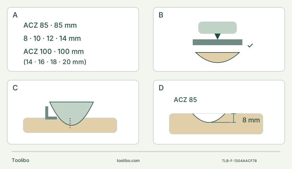
A · Match diameter and marking
The 85 mm ACZ 85 scale is 8/10/12/14 mm in large unparenthesized marks. The 100 mm ACZ 100 scale is 14/16/18/20 mm in smaller parenthesized marks; do not read it for this 85 mm blade.
B · Assemble and fully reseat
Unplug, cool and use change gloves. Remove the accessory, slide the marked-up stop fully onto the neck, AutoClic the correct segment blade and check retention. Pull the stop forward to rotate, align the selected mark and push it back fully.
C · Cut only with a usable reference
Clamp a fully visible sample and clear the whole segment envelope. Keep both hands on insulated grips, switch reachable and the stop on the intended flat face; stop and isolate if reference or support changes.
D · Record, accept or stop
Stop, wait, unplug and inspect the exposed kerf section. Compare the actual observation with the nominal 8 mm target and intended purpose; unexplained depth, damaged parts or poor retention means correction or service, never extra force.
Original schematic, not dimensional or measured evidence. A shows both manual scales, but the selected blade is ACZ 85 EB only. B means stop first, then AutoClic blade engagement; adjustment requires pull toward blade, rotate the correct marking over the cutting portion and push back fully. C shows reference contact, not permission to rock or force below the stop. D labels the nominal 8 mm target; actual depth is observed only after stopping and unplugging, with no invented tolerance.
A stop-setting trial, not permission to cut an installed surface
This project produces one shallow, inspectable kerf in a clamped piece of known loose solid softwood. Its purpose is to choose the correct depth scale, install the PMF 350 CES segment stop and compare the isolated result with the selected nominal setting. It does not make a stopped cut safe above wiring, pipework, flooring or an unknown back surface. If the underside and complete blade envelope cannot be inspected, this exercise does not apply.
Use the exact French PMF 350 CES covered by E64, dated 2 April 2026, with matching actual nameplate, regional supply and supplied instructions. The selected accessory is the actual Bosch ACZ 85 EB BIM Wood and Metal segment blade, 85 mm, part 2 609 256 943, listed on the exact French product page. The same page identifies the four-position segment stop, part 2 609 256 C61. Confirm the physical parts; a current listing does not prove what remains in an owner’s case. The E64 segment-blade table includes wood, but this project deliberately excludes metal, unknown coatings and installed material.
A straight plunge blade does not become a stopped blade merely because it fits AutoClic. The stop procedure is for the specified segment-blade diameters. Do not substitute another diameter, add a spacer or use an unrelated stop to obtain a desired number.
Read the correct scale before planning the cut
E64 gives two different sets of stop markings:
- With an ACZ 85-series segment blade of 85 mm diameter, the large unparenthesized marks correspond to 8, 10, 12 and 14 mm.
- With an ACZ 100-series segment blade of 100 mm diameter, the smaller parenthesized marks correspond to 14, 16, 18 and 20 mm.
The second row explains the alternate scale; it is not a second accessory selected for this trial. With the actual ACZ 85 EB, choose the large 8 mm marking. Reading the parenthesized number on the same stop would select the wrong blade/setting combination. Blade diameter alone also does not establish material approval: verify the exact blade identity and instructions.
For a hypothetical practice specimen, consider a flat 20 mm-thick softwood offcut with enough area for stable clamping and the complete stop footprint. That thickness is a project example, not a manufacturer minimum, capacity or guaranteed safety reserve. Measure the actual specimen, reject an unsuitable one and inspect all space below it. The stop is not a depth certificate; blade condition, seating, work support and tool attitude still need checking.
Place the proposed shallow kerf so its section can be inspected at an exposed edge after isolation, without cutting off a loose piece. Mark only a short straight route. Verify that the whole segment’s toothed arc and the stop can approach without touching clamps, support, retained surfaces or your hands. Do not select a narrow pocket whose corners require twisting the segment blade. Leave adequate flat material for the stop to bear on; a rounded, broken or sloping reference surface defeats this sample’s purpose.
Before setup, inspect the chosen wood and complete cut route for nails, screws and other foreign material; reject any such specimen for this clean-wood-only trial. Clamp the specimen to a stable platform outside the entire swept envelope and keep both faces visible. Do not put a hand underneath as a depth indicator. If the sample would rock, the stop would overhang its reference surface or the blade would hit the bench, rearrange the setup before mounting or choose another sample.
Install the stop before the segment blade
Set the switch to 0, wait for complete stop and unplug. Inspect the cable, actual stop, holder and blade. A damaged stop, bent or dull blade, doubtful mounting interface or damaged auxiliary handle means no trial. Let hot accessories cool and wear protective gloves for changes; the segment teeth remain sharp while stationary.
Remove any installed accessory by opening the AutoClic lever fully to its stop. The accessory is ejected: arrange safe support and do not catch a hot or sharp falling blade. Slide depth stop 12 over holder 8 onto the tool neck, with its marking upward, and push it fully to the stop. It is not installed on top of an already clamped blade.
Fit the selected segment blade in the useful orientation, with depressed centre down and lettering readable from above. Press the tool onto the accessory until engagement is audible, then check secure retention. Do not import a bolt, torque or adapter procedure. The E64 chart permits Starlock and StarlockPlus, not StarlockMax; the actual selected blade must also match its intended use.
With the tool still unplugged, pull the depth stop toward the accessory until it can turn freely. Rotate it until the desired large 8 mm marking lies above the part of the blade that will perform the cut. Then push the stop back fully onto the tool neck. This final reseating is part of the setting, not an optional storage position. Check the chosen mark, relevant cutting portion and full seating together. If the stop cannot seat or remain correctly oriented, do not hold it in place with a hand during use.
For other depths or other accessories, the manual directs removal of this stop: first remove the working accessory, then slide the stop off the neck. Do not promise arbitrary intermediate depths by leaving it partly seated. A change to the selected blade or angle requires another unplugged setup check and a new appropriate trial.
Make one controlled sample
Fit the intact auxiliary handle to the designated side thread. Hold the tool firmly with both hands on insulated gripping surfaces, leave vents clear and make sure the I/0 switch remains reachable without releasing the handle. Route the cord well away from the segment and movement of the tool. Match the actual supply voltage and confirm 0 before connection. Slide the switch forward to I to run and backward to 0 to stop. Do not look directly into the LEDs. Soft start and constant electronics do not justify assuming restart protection.
Wear eye and hearing protection, always use appropriate respiratory protection, ventilate and take dust-reduction measures. Use suitable material-specific extraction where possible. The PMF sanding attachment is not a segment-blade dust hood, and the sanding-only installed performance table cannot be used to claim capture here.
Wood sawing permits a setting up to 6, subject to a lower limit on the actual accessory. Choose a controllable setting for equivalent scrap; E64 supplies no exact initial-entry setting for this task. Set it with the tool stopped for this exercise. Start with the blade clear, then enter the marked short route with moderate, even pressure and a stable tool attitude. Keep the stop’s working reference against the intended flat face without rocking it over an edge. The stop limits the selected geometry; do not press harder to force the blade below it.
Use the manual’s controlled back-and-forth cutting motion to reduce heating and binding, without twisting the segment in the kerf or widening the slot with side force. Keep hands away from the cutting zone and underside. Plunge cutting is limited to soft materials such as this known wood. If the stop loses its reference, the stock moves, the blade binds or abnormal behaviour occurs, stop, wait and unplug before correction. Do not continue by feel or run another pass just to reproduce the problem.
Measure only after isolation, then decide
At the end of the short trial, select 0, wait for complete standstill and unplug before setting down the tool, touching the specimen or bringing a measuring tool near the blade. Let the blade cool. Inspect the exposed kerf section and measure its deepest visible cut from the original flat reference face with a suitable measuring tool. If that section cannot be inspected reliably, do not claim a measured result; choose a different sample arrangement rather than probing beside an energized blade.
Compare the observation with the nominal 8 mm setting and the intended shallow-cut purpose. Check for unexpected breakthrough, overshoot into retained material, shifted support, scorch, rocking marks and any loss of stop or blade retention. The diagram’s 8 mm label identifies the selected target, not a photographed measurement or guaranteed tolerance. Record the actual observed result rather than rounding it to the label.
An acceptable trial has a securely seated system and an inspectable result consistent with the selected setting and planned purpose, without those defects. If it does not, leave the tool unplugged, verify the exact diameter/scale, blade orientation and full stop seating, and correct the support. Damaged parts, unreliable retention or an unexplained discrepancy require qualified service, not an invented offset or extra force. Even an accepted loose sample does not authorize a blind installed cut or establish structural fitness.
Remove and store the cooled sharp accessory safely after the task, keep the tool and vents clean as instructed and protect the cord. Source basis: PMF 350 CES E64 French safety and compatibility pages 25–27, stop/AutoClic page 29 and operation pages 30–31, actual Figures A–C; exact French product accessory listing. No hands-on result is claimed.
Models referenced