
AutoClic engagement, reachable controls and sanding-only extraction
Three panels show tool pressure onto an accessory, the auxiliary handle with automatic 180-degree light and I/0 control, and a sanding-only extraction gate with both required installed values.
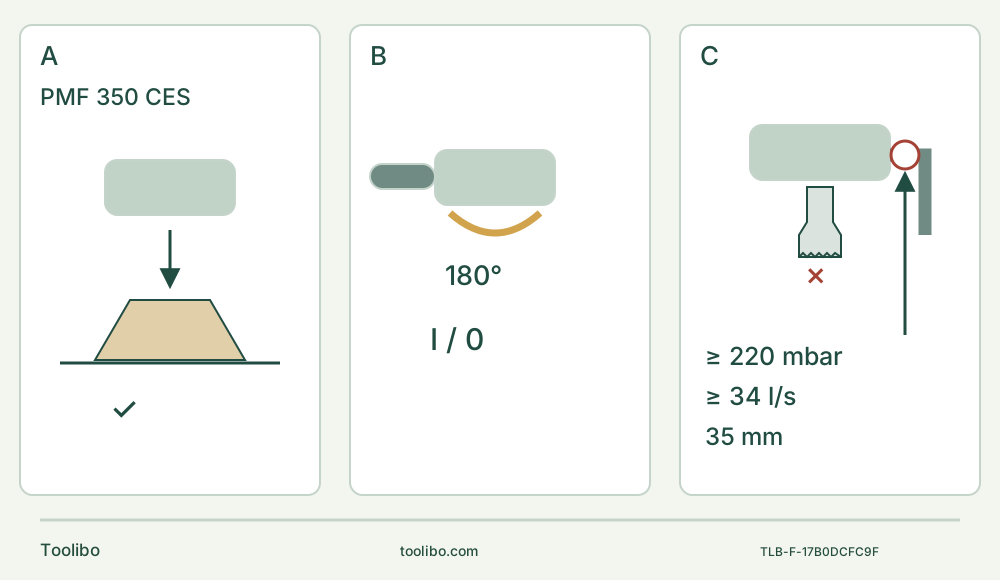
A · Isolate, eject and engage
Select 0, wait and unplug. Let the accessory cool, wear change gloves and open the lever fully for controlled ejection. Press onto the correctly oriented Starlock or StarlockPlus accessory until audible engagement and verify retention.
B · Qualify grip, light and wood controls
Fit the intact auxiliary handle and route the cord. I runs and 0 stops; the 180-degree light follows the switch. A sound AIZ 32 EPC on clamped visible wood uses a controlled setting up to 6, subject to its own limit.
C · Keep sanding separately qualified
Device 18 is for the sanding pad only. Sanding needs at least 220 mbar and at least 34 l/s at the tool connection, suitable filtration and the actual extractor instructions; recommended 35 mm hose alone proves none of this.
Original schematic, not counted holder geometry. A means unplugged pressing until audible engagement followed by a secure-seat check, not a freehand workholding example. B shows the light span, not a lever rotation; keep both hands on insulated grips and the switch reachable. C crosses out use of this attachment for a saw blade; the circle marks the tool-side connection where both minima apply. The 35 mm hose is recommended, not an independent sufficiency test.
Match the French body and the E64 instructions
This project ends with a small, visible cut in a clamped piece of new, uncoated solid softwood, followed by an unplugged inspection. It does not authorize a cut in installed trim, a wall, flooring or an unknown panel. The selected system is the French PMF 350 CES associated with order 0603102200 and the linked E64 instructions, dated 2 April 2026. Match the actual nameplate, regional supply and supplied instructions before using this sequence. The manual identifies the body family as 3 603 A02 2..; an order number is not a substitute for that physical check.
The technical table is based on 230 V and identifies a Class II corded body. Use the supply stated on the actual tool, inspect the cable and plug, and do not improvise a regional plug or damaged-cord repair. The product page and manual label their speed figures differently; this guide does not convert those labels into a new specification or promise a rate at each dial position. Its operating authority is E64, not the older A9G download also linked by Bosch.
For this project, identify the actual Bosch AIZ 32 EPC HCS wood blade, part 2 609 256 947, listed on the exact product page. Its nominal 32 × 40 mm description is not a guaranteed usable plunge depth. Confirm the installed reach, swept tooth envelope and material approval on the actual accessory. Do not assume every owner’s box still contains that blade or that a similar-looking accessory is equivalent.
Make the work visible before selecting a mounting angle
Choose a small offcut whose species, condition and history are known. Reject coated, treated, contaminated, nailed or otherwise uncertain stock for this exercise. Inspect both faces and the entire route below the intended cut; there must be no electrical cable, fixture or hidden object behind it. An HCS wood blade is not permission to cut embedded metal. Use only a sound, sharp blade: bent, damaged or dull blades can break or kick back.
Mark a short straight cut that the actual blade can complete without forcing its sides or exceeding its reach. Clamp the retained stock to a stable bench and arrange separate support for the waste so it cannot drop into the blade, pinch the kerf or move the retained piece. Keep clamps and supports outside the complete cutting envelope. Leave access for both hands and for the switch; neither a hand under the board nor a person holding the waste is a support system. If this arrangement cannot be made visible and stable, change the sample rather than attempting an installed-work shortcut.
The tool accepts Starlock and StarlockPlus accessories; the E64 compatibility chart rejects StarlockMax. That is a holder-tier boundary, not approval of every material, shape or task sold under those names. The straight wood blade here needs neither the segment-blade depth stop nor the sanding extraction attachment. Remove those accessories when they do not belong to the selected setup. In particular, the segment stop is not a depth limiter for AIZ 32 EPC.
Unplug, eject and press until AutoClic engages
Select 0, wait for all motion to stop and unplug before any setup or accessory change. Let a hot accessory cool and wear protective gloves when handling or changing it. Keep clear of its teeth and plan a safe receiving surface: opening the AutoClic lever fully to its stop ejects the installed accessory. Do not catch a hot or sharp falling blade in your hand.
For installation, place the selected accessory in a useful working orientation with its depressed centre downward and its lettering readable from above. Press the tool onto it until engagement is audible, as shown in E64 Figure B. Check that the accessory is securely seated before proceeding. AutoClic uses press-engagement; do not transplant a bolt, washer, adapter or tightening procedure from another holder. Failure to engage or retain securely is a stop-and-service condition, not a reason to test the clamp under power.
Screw the intact auxiliary handle into the designated side thread on either side as appropriate for access. Do not modify it or continue with a damaged handle. Establish a stable two-handed grip on the insulated gripping surfaces, leave the ventilation openings clear, and keep the switch reachable without releasing the handle. Route the cord away from the blade, waste and your movement. Insulated gripping surfaces remain important because the accessory could contact the tool’s own cable.
Set the controls for this wood trial
Before connection, confirm 0, secure clamping, clear hands and a sound cable route. Wear eye and hearing protection, ventilate the work area and always use appropriate respiratory protection. E64 requires measures to reduce dust emissions and suitable material-specific extraction where possible; a clean-looking sample does not remove the dust requirement. The dedicated attachment discussed below works with the sanding pad only, not as a saw-blade capture hood.
Move the switch forward to I to run and rearward to 0 to stop. The 180-degree light switches with the tool; do not look directly into the LEDs. Soft start and constant electronics do not establish automatic restart protection. Keep the switch at 0 during any interruption before reconnection rather than relying on those features to prevent a start.
E64 permits a maximum dial setting of 6 for wood sawing, subject to any lower accessory limit. Determine the useful setting by a controlled trial in equivalent scrap; there is no exact initial-entry number or dial-to-rate table supplied here. Although the manual allows adjustment while running, choose settings with the tool stopped for this project. Sanding, plastic/metal cutting and carbide-grit accessories have a maximum setting of 4; those limits must not be replaced by the wood setting.
Start with the blade free of the sample, then make a controlled entry at the marked route. Plunge cuts are limited to soft materials such as the selected wood. Apply moderate, even pressure and move the tool back and forth along its intended cutting route to limit heating and binding. Do not twist the blade to create a wider opening, lever out a remaining bridge or force a stalled cut. Keep both hands away from the cutting zone and underside. If the support moves, the blade binds, retention becomes doubtful or abnormal behaviour appears, stop, wait and unplug before investigating; do not reproduce the fault for a test.
At completion, stop the tool, wait for complete standstill and unplug before touching the work, changing the setup or inspecting the edge. Never set the running tool down. Allow the blade to cool before removal. With the system isolated, check that the cut follows the intended line and fully separates the intended waste without uncontrolled tear-out, scorch or displaced support. A remaining bridge or poor result calls for a corrected, re-clamped setup or service, not hand-breaking the piece beside an energized blade. No dimensional tolerance is invented here: compare the finished sample with its marked purpose before accepting it.
Sanding is a separately qualified system
Do not infer that completing the cut makes the tool ready for sanding. Switch to 0, wait for full stop and unplug before installing or removing any sanding or extraction parts. This is dry sanding only. Control overheating and fire risk: avoid excessive heating of the tool or work, and empty dust collection before breaks under the actual extractor instructions. Dust can ignite, especially in mixtures or with hot residues. E64 requires a vacuum for sanding and both at least 220 mbar vacuum and at least 34 l/s airflow at the tool connection. These are installed requirements, not a vacuum motor’s advertised rating. A 35 mm hose is recommended; HEPA or class M filtration is recommended under IEC/EN 60335-2-69. The actual extractor must suit the material and its own instructions must be available. If this qualification is missing, leave sanding pending.
For the documented tool-end assembly, remove the current accessory and depth stop. Slide extraction device 18 fully over holder 8 onto the tool neck, turn it to a suitable position—not directly underneath the tool—and close clamping lever 19. Snap adapter 16 audibly into hose 15, connect the adapter to outlet 17 and the hose to the suitable extractor. Fit the matched sanding pad through the same AutoClic sequence. Clean the hook-and-loop surface, place the matching sheet flush at one edge and press it over the entire pad; align all extraction holes. The manual allows the specified 93 mm triangular Bosch sanding materials, not arbitrary pads whose outline merely looks similar.
Use no more than setting 4 and obey any lower accessory limit. Excess speed or pressure promotes wear and heating; do not reuse a sheet previously used on metal for other materials. Reduced filtration performance requires stopping and finding the cause under the actual equipment instructions, not continuing because the hose still makes a noise. Device 18 is expressly ineffective with the other working accessories shown crossed out in Figure C. It is not a universal cutting-dust solution.
Close the job without opening the tool
Unplug, let hot parts cool and clean the exterior and ventilation openings as instructed. Retire damaged accessories; keep the cable protected in storage. A damaged mains cable requires Bosch or an authorized service facility, not an owner splice. If AutoClic cannot securely retain the proper accessory, the switch is unreliable or the tool behaves abnormally, keep it out of use and provide the service provider with the exact nameplate and ten-digit product reference.
Source basis: PMF 350 CES E64 French instructions, pages 23–32 and Figures A–C on pages 4–5; exact French product identity and AIZ 32 EPC listing. This is a documentation-based owner workflow, not a hands-on performance test or a guarantee of current kit contents.
Models referenced