
From blade envelope to accepted opening
A contrasts narrow and broad neutral blade silhouettes and their full envelopes. B shows corner and back-face overrun concerns. C marks supported retained stock and central waste. D compares both faces after electrical isolation.
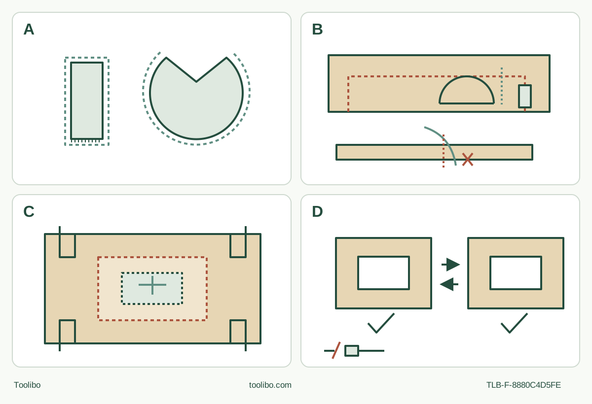
A · Qualify shape and complete envelope
Actual MM480 and MM450 identities, rating and softwood approval come first. A narrower profile still needs its full oscillation and holder clearance.
B · Check the corner on both faces
A curved edge can cross the back-face boundary differently. Choose a qualified end-cut sequence or reject the route; do not twist or bend a blade.
C · Support what will separate
Clamp retained stock and separately support waste outside the full blade path. Reposition only while unplugged.
D · Isolated acceptance determines the choice
Check size, line, breakthrough and corner overruns on both faces. A failed sample does not justify buying more blades blindly.
Original schematic, not to scale and not an installation-interface drawing. Dashed envelopes require actual geometric checks, not a fixed allowance. B warns against back-face overrun; C central cross identifies waste needing separate support, never a hand position or support directly beneath the blade. D checks both faces only after OFF, full stop and unplugging.
Buy for the complete cut, not the blade silhouette
A narrow plunge blade and a broad flat saw blade can both be approved for softwood, yet fit very different paths. This decision guide compares the actual MM480 HCS wood flush-cut blade and MM450 three-inch wood/drywall saw blade listed in the August 2018 US MM35 manual. It concerns an existing matching 120 V, 60 Hz MM35 and identified Dremel accessories rated at least 21,000 OPM. It does not establish current availability, a current kit’s contents, or equivalence to an accessory with a different suffix.
The project is a small rectangular opening in a removed, loose, uncoated solid-softwood sample with both faces accessible. Nothing is installed over wiring, plumbing or a concealed cavity. The buying outcome is one qualified blade, a justified two-blade sequence, or no purchase because neither complete path works. This is not a speed contest or a hands-on performance test.
Use the MM35 manual’s accessory table on page 13 together with its assembly pages 8–10 and operating instructions on pages 11–15. The table identifies MM480 as a 1-1/4 by 1-11/16 inch HCS wood flush-cut blade and MM450 as a three-inch wood/drywall saw blade. Those descriptions are not universal usable cutting depths: the actual holder, angle, exposed teeth and work geometry still limit reach.
Gate one: material approval before approach
Confirm known solid softwood through the whole cut. Remove the sample from any assembly and inspect both faces, edges and underside. Painted or treated stock, unknown reclaimed wood, embedded nails and a laminated panel are outside this worked example. Do not transfer MM482’s metal columns to MM480, or assume a word such as “wood” approves every coating and composite.
The exact table gives both selected blades softwood settings 8–10 and hardwood settings 6–10. Here only the softwood row is used. A blank or dash is not permission, and a speed setting is not a material-identification method. The flat saw discussion also notes that it works best in softer woods and has limited blade life in harder woods; that is not a comparative durability score.
Identify the actual accessory and its rating before buying or installing it. A seller’s picture of a similar blade, an open mounting slot or a “universal” claim cannot close this gate. If an exact matched accessory cannot be identified, pause for manufacturer evidence instead of adapting an unknown one to the clamp.
Gate two: draw the swept path on both faces
Mark the finished rectangle and identify which side of each line is waste. Inspect the required entry points, line lengths and corners. With the tool unplugged, compare the actual blade’s full oscillating envelope and the holder/body approach with the available space. Include the underside, supports and clamps. Do not energize a blade to discover its clearance.
A narrow straight blade is the candidate where a short line or tight end location needs a relatively narrow approach. It still has width, thickness and side-to-side movement; it is not a point cutter. If the blade’s width exceeds the planned opening or its holder strikes the work before reaching through, the candidate fails. Turning it sideways cannot create free clearance, and bending it is not an approved adaptation.
The broad MM450 is a candidate where a longer accessible line and generous surrounding clearance allow its curved cutting edge to work. Its shape does not make it automatically better for every straight cut. Consider the entire blade, not just the teeth touching the visible face. A curved edge can intersect the hidden face differently from the visible line; stopping at a corner on top does not demonstrate that the back face has stayed inside the boundary.
Do not assign a universal corner allowance from the three-inch diameter. The actual approach and measured sample thickness control the geometry. If both faces cannot be inspected, or any overrun cannot be kept entirely within waste and clear of retained material, this project does not qualify. Choose another documented method, not a deeper blind pass.
Two worked selection decisions
Short opening with close corners. Suppose the marked opening leaves little room beyond each line and a broad arc would extend into retained material. Select the identified MM480 only if its actual width, reach and complete envelope fit every entry and corner. Plan separate controlled entries; never twist an engaged blade to turn a right-angle corner. If the remaining corner cannot be completed without overcutting, reject the plan before purchase. There is no promise of a perfectly sharp internal corner merely because the blade is straight.
Longer open line with accessible ends. Suppose the removed sample has ample clear space for the MM450’s arc and the back face remains visible. The MM450 may qualify for the long sections after an isolated geometric check and scrap trial. If its arc cannot complete the ends cleanly but the MM480 can, a two-blade plan is reasonable: stop, unplug and complete the entire mounting procedure each time the blade changes. The second accessory is justified by a distinct unfinished path, not by a larger kit looking like better value.
If only one blade can perform all required cuts within the retained boundaries, there is no need to buy the other for this job. If neither works, neither is the correct purchase. This comparison does not substitute an unreviewed rotary tool, jigsaw or another brand’s adapter as a shortcut.
Gate three: support the piece that will become waste
Clamp the retained panel to a stable platform and separately support the center waste so it cannot fall, pivot or pinch the blade as the last line is cut. Keep every clamp and support outside the full cutting path. Plan the order of cuts before starting, including where both hands and the cord will be during the last connection.
The central cross in the diagram marks the waste area requiring support; it is not permission to hold the center by hand or put a support directly beneath the blade. If clamping or support must move, turn OFF, wait for full stop and unplug first. Recheck both faces and the entire path after repositioning. An otherwise suitable blade does not rescue an unstable workholding plan.
Install the chosen blade completely
Slide the switch backward to OFF, unplug and let hot accessories cool. Wear protective gloves for changes and operation. Loosen the clamping knob counterclockwise, then press it to extend the flange enough to admit the accessory. Seat the identified blade against the holder, engaging every pin and lying flush. Release the knob, then turn it clockwise until fully hand-tight as the manual describes—until further turning would be uncomfortable. Temporary spring retention is not the final clamp.
An angled installation is allowed only with the same full pin engagement, flush seat and complete tightening. No pliers, added washer, guessed torque or modified slot is supplied by this procedure. If the blade will not seat and secure correctly, stop. For removal, unplug, loosen and press the knob, then lift the cooled accessory off the pins. Treat the two selected blades as two complete installations, not a quick powered swap.
Prove the choice on a prepared sample
Use sound matching mains power and an intact cord routed behind the work, away from teeth and pinch points. Avoid an unnecessary extension; if one is needed, select it from the exact manual’s rating/length table rather than inventing a cable size. Do not raise speed to compensate for faulty supply or abnormal starting.
Before each use, inspect the actual blade for cracks, breakage, bending and dullness; reject it if damage is suspected. Wear eye and hearing protection, protective gloves and appropriate dust protection; work with ventilation, stable footing and a clear area. Hold the insulated gripping surfaces with both hands, keep hands away from the cutting area and out from under the material, and leave vents clear. Check the dial separately from the slide switch. The table’s 8–10 softwood range does not override page 15’s instruction to begin the initial plunge at medium speed for control, then increase after establishing the initial cut. “Medium” is not a newly specified exact numbered setting. The ten-position dial is not OPM in thousands.
With the accessory clear and the setup ready, connect power with the switch OFF, then slide forward to start. Guide lightly, using repeated controlled passes rather than forcing full depth at once. Do not twist the blade in the cut or use it to lever out the center. Strong vibration, binding, moving stock, unusual behavior or lost clearance means stop, wait and unplug before investigating. Do not repeatedly restart to push through a rejected geometry.
After the cuts, switch OFF, wait for complete stop and unplug before removing supported waste or checking the result. Inspect both faces for line and size, complete separation, unintended corner overruns, tearing and scorching. Reject a result that does not meet the actual opening requirements; do not hide an overcut by calling the blade “precise.” No numerical tolerance or structural acceptance is implied.
The final buying record should name the actual blade or justified pair, matched material, permitted approach, support plan and successful isolated sample inspection. If any remains unresolved, keep the job and purchase on hold. Compatibility is only the first gate; a complete usable cut is the outcome.
Models referenced