
Original hardware, actual controls and supported separation
A shows a separated battery and nonstacked original bolt, outer flange and 5 mm hex-key inventory. B shows a neutral blade-identification document gate, not an approved universal mounting shape. C pairs dial endpoints 2/5,000 OPM and 12/20,000 OPM with I/0 slide cues. D shows a retained clamp, independent waste support and clear blade exit.
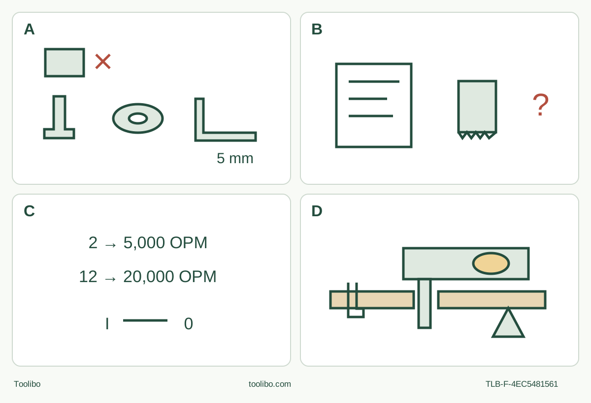
A · Isolate and inventory
Remove the battery before original bolt/outer-flange/accessory removal; use the correct 5 mm key and no borrowed hardware.
B · Qualify the no-adapter blade
Match actual recommended original wood blade, material and complete chart profile. Uncertain or adapter-dependent routes stay held.
C · Use the actual endpoints
Dial 2 is 5,000 OPM, 12 is 20,000 OPM. Slide I only with a clear blade and allow full selected speed before contact; rearward 0 stops.
D · Separate and inspect
Clamp the retained stock, independently support waste and keep the full blade envelope clear. Stop fully and remove the battery before acceptance.
Original conceptual schematic. A is an inventory, not an exploded mounting order or torque instruction. B requires actual original blade/material/no-adapter profile evidence from the complete manual chart; no generic opening is approved. C shows endpoints, not a numbered wood setting or test instruction. D represents full-path support without a cutting-depth rating or exact grip contour.
Identify the original blade before opening the clamp
This guide covers an existing US Milwaukee 2426-20 M12 multi-tool with matching controls and operator’s manual 58-14-2426d4, revision 10/21. It is the separate-outer-flange, accessory-bolt and 5 mm hex-key body, not the lever-operated 2526 or an M18 Auto-Load tool. The 2426-22 package is not a second body, and a current product listing is not proof of what is in an owner’s case.
The project is a complete short separating cut through known, dry, uncoated loose softwood, with the retained piece clamped and the waste independently supported. Before proceeding, positively identify the actual original recommended wood-cutting blade, its intended material and its mounting profile. Match its actual instructions and permitted reach/rating to this tool and task. The exact current product identifies a wood-cutting blade, but this guide does not invent a part number, cutting capacity or current-kit guarantee. An unmarked blade, an uncertain replacement or an unclear material approval is a hold for manufacturer or qualified-supplier identification, not permission to try it because it fits.
For this project the actual blade must match a no-adapter profile in the selected manual’s chart. That chart has six depicted profiles: two need no adapter and four require a separately sold adapter with a specified face toward the accessory. Similar-looking holes are not a universal fit rule. All adapter routes remain outside this project; do not attach a brand, OIS or Starlock label to an unlabelled silhouette, or borrow another tool’s bolt or flange.
Power, conditions and the visible cut route
Use only an already commissioned original M12 battery system, with the actual approved battery/charger combination and its own instructions available. The tool manual specifies M12 battery and charger types but directs charging details to their manuals. It does not establish a new named pair for this project. Damaged, modified, wet or unexplained equipment is not a qualified system. The stated recommended ambient operating range is 0°F to 125°F; it is not a charging-temperature recipe.
Slide the actual switch back to OFF, marked 0, wait for complete standstill and remove the battery by pressing its release buttons and pulling it away from the tool. The manual contains a generic instruction about locking a trigger or removing the battery, but this body is operated by a slide switch. Do not invent a trigger lock: use known OFF and full battery removal for setup, storage and accessory work.
Inspect the isolated housing, handle, switch, inner and outer flanges, original bolt, hex key and blade. Reject cracked, bent, dull or otherwise damaged accessories and any suspect clamp, loose hardware or unreliable control. An uncertain condition needs qualified correction, not an energised seating or wobble test. Let hot accessories cool and handle sharp edges carefully with protective gloves; never put hands near a moving edge.
Use a sound workpiece with no hidden construction history, coatings, treatment or embedded foreign material. Mark the short cut and examine both faces and the whole exit path. The actual blade must reach through without the housing hitting the stock, and the oscillating accessory must clear the bench, clamps and support throughout. Do not turn blade length into a manufacturer-rated cutting depth. If the opening, blade or support cannot maintain that clearance, choose a different qualified process instead of forcing a plunge.
Clamp the retained piece to a stable platform. Support the waste independently so it cannot drop unexpectedly, close the kerf or pinch the blade; do not bridge the intended separation with a rigid clamp. Keep both the path and surrounding work area visible, dry and well lit, with stable footing and bystanders clear. Do not hold the work against your body or in a spare hand. There are no installed pipes, cables, services or blind-wall assumptions in this task.
Wear eye protection marked ANSI Z87.1, hearing protection appropriate to the work and other required PPE. For dusty work the manual requires appropriate respiratory protection or an OSHA-compliant extraction solution; that alternative does not remove eye or hearing protection. Use ventilation. If extraction is the chosen solution, correctly connect, operate and check it under its actual equipment instructions before cutting; do not imagine a native capture fitting. Unknown dust-producing materials remain excluded.
Rebuild the original no-adapter stack while isolated
With the battery fully removed, place the tool upside down on a flat, stable surface. Use the original 5 mm hex wrench to remove the accessory bolt. Remove the outer flange, the old accessory and any fitted adapter. Do not leave an old blade hidden in the stack or transfer an adapter automatically to the replacement.
Clean dirt and debris from the bolt, inner and outer flanges, old adapter and selected accessory without altering their mating surfaces. Stop if the original parts are missing, damaged or cannot be identified. Cleaning is not permission to file a flange, grind an opening, add a washer or force a different bolt into the tool.
For the positively matched no-adapter blade, position the accessory at an angle that allows the whole planned approach. Refit the actual original outer flange and accessory bolt in the illustrated sequence, and tighten securely with the correct hex wrench. The manual supplies no numerical torque here; do not invent one or use impact tightening. Check that the accessory is correctly seated and secure while the battery is still out. Remove the wrench and loose parts from the work area before any later battery insertion.
Keep the full six-profile chart available for identification even though this cut uses neither adapter face. A profile requiring an adapter is a different unresolved equipment route, not a reason to flip any loose disc until something seems to tighten. Obtain the exact accessory and adapter instructions if a future task genuinely needs that route.
Make the cut with the actual slide switch and dial
Confirm OFF, a clear blade, secure stock and waste support, correct grip and no wrench left attached. Insert the qualified charged pack into the body until it latches securely. Grasp the designated handle, keeping hands away from every cutting edge, moving part and the underside of the workpiece. Maintain control without using the metal clamp area as a handhold.
This dial’s endpoints are 2 for 5,000 OPM and 12 for 20,000 OPM. Do not substitute another Milwaukee tool’s level 1 or an A mode. For sawing/cutting the manual directs a high speed, within the actual blade’s instructions and limits; it does not provide a particular intermediate wood setting. If those limits cannot agree, stop and resolve them rather than choosing a convenient number.
With the blade clear, slide the switch forward to ON, marked I. Allow the tool to reach the selected full operating speed before contacting the wood. Follow the marked route using controlled, moderate pressure. Excessive force can scorch the wood or bind the blade; the sharp intact accessory should do the cutting. Keep the full underside and exit envelope clear as the blade advances. Do not twist the blade or lever the waste free to finish an incomplete cut.
Stop for changing vibration, slipping stock, accessory movement, burning, binding or any abnormal sound. Move the switch to 0, wait until motion has ceased and remove the battery before investigating. Do not restart just to watch a suspected loose attachment or reproduce a fault. If support or access has become inadequate, rebuild the isolated arrangement or choose another process; a new battery is not the answer to a mechanical obstruction.
At complete separation, switch to 0 and wait for full standstill before withdrawing on the clear path and setting the tool down. Remove the battery before handling the blade, moving supports or inspecting the pieces. A cut is accepted only when it follows the intended line/size, has fully separated without uncontrolled tear-out or scorching, and shows no evidence that the stock or support shifted. Otherwise record the defect and correct the setup before another sample. No invented dimensional tolerance or structural fitness claim is implied.
Read this body’s signals, not a newer model’s pattern
During an ordinary qualified start, the fuel gauge lights for two to three seconds. With less than 10% charge remaining, one light flashes four times. At the end of charge, one light flashes eight times and the tool will not run; follow the actual charging instructions only for a sound qualified pack. If the battery is too hot, the gauge lights flash and the tool will not run; allow it to cool as instructed. The source does not assign an alternating pattern or a particular colour to this hot-battery indication.
Do not turn the tool on solely to diagnose an uncertain fault. If it stops, establish OFF, standstill and battery removal before assessing the cause. Repeated or unexplained shutdown, failure with a known qualified system, or damaged equipment requires service. There is no imported no-load cooling run or trigger-cancellation sequence. A gauge cannot establish pack capacity, authenticity or safe condition.
Close the project and preserve the service evidence
Keep the battery removed for tool care; unplug the charger and remove its pack before any charger maintenance. Inspect accessible parts and vents, keeping the system clean and dry. The manual permits mild soap and a damp cloth for exterior cleaning, not immersion or fluid entry, and warns against damaging or combustible solvents. Do not disassemble the tool, battery or charger. Its contact-cleaning instruction is not authority to scrape, bridge or rebuild terminals; if safe documented external care does not resolve a problem, use authorised service.
The manual calls for service inspection after six months to a year depending on use. That is not an owner internal-repair interval or a guarantee that a tool is sound until then. Retain the exact catalogue and serial identity, matched instructions, original hardware and a record of any abnormal condition for the service provider. Store the cooled blade protected, the switch OFF and the battery separated safely under its own instructions.
The useful result is a fully separated, inspected sample and an isolated complete system. If identity, power, clamp parts or blade suitability never closed, a clear hold with the missing evidence is the correct result instead.
Evidence: current US 2426-20 product/manual bridge and operator’s manual 58-14-2426d4, English pages 2–6, actual assembly/chart page 4 and controls/signals page 5, footer revision 10/21. No hands-on cutting or performance comparison is claimed.
Models referenced