
Clamp, cut and distinguish the gauge signals
Three panels show battery removal and accessory bolt separation with a conditional adapter number, a clamped wood cut and dial range, and four-flash, eight-flash and alternating gauge patterns.
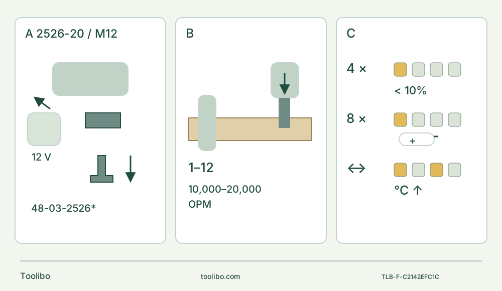
A · Complete lever and bolt
Remove the battery, push the lever past the detent, invert and unscrew the bolt. Clean and seat the approved accessory, hand-tighten securely and return the lever.
B · Make the visible cut
Clamp and support known loose wood. Dial 1 is 10,000 OPM and 12 is 20,000; sawing uses a suitable high setting and moderate pressure, with full speed before contact.
C · Do not confuse the patterns
One light four times means below 10 percent; eight times means depleted/no operation. Alternating lights mean a hot battery/no operation. Set OFF and respond through the qualified power-system instructions.
Freshly reviewed original schematic. The adapter asterisk means only the two arbor shapes in the matched manual; indicator colors are illustrative, not diagnostic specifications. The support sketch is not a complete bench plan.
Make the first “repair” a visible bench task
This owner workflow is for the US Milwaukee 2526-20 M12 FUEL, matched to the current official product-linked manual 58142526d2, revision 05/20. It is documentation-based, not hands-on testing. This exercise is a short cut in loose, known, unfinished softwood on a stable bench. It does not approve cutting an installed wall, floor or trim with an unknown back face.
Confirm the body label and controls, then read the supplied tool and power-system instructions. A similar-looking M18 model, a kit suffix or a general accessory advertisement is not a substitute. The outcome is a cleanly controlled cut, a correctly stopped and isolated tool, and a clear response to the M12 gauge signals—not simply getting the blade to move.
Use an already qualified M12 power system
The tool is rated 12 V DC and specifies M12 batteries and M12 chargers. This guide assumes an undamaged genuine M12 battery and compatible M12 charger already commissioned under their actual instructions. Verify the physical labels and retain those instructions. It does not establish a new charging installation, choose an exact battery capacity, assign charger input voltage or supply charging temperatures. If the pair has not been qualified, stop before powering the tool.
The manual’s recommended ambient tool-operating range is 0–125°F; that is not a battery-charging range. Do not use modified or damaged batteries, expose terminals to loose metal, immerse the system or open a pack. Unusual noise, binding, damaged parts or an unreliable switch requires repair before use.
Move the switch backward to OFF before inserting or removing the battery. Press the pack release buttons and pull the pack away from the tool. Remove it before every accessory change, adjustment, inspection and storage. Later, slide it into the body and verify the latch has engaged securely, with OFF already selected. A dark gauge or an OFF switch alone does not replace physical battery removal.
The lever releases tension; the bolt still needs attention
Choose a sharp, undamaged cutting accessory specifically recommended for this tool and approved for the actual wood. Check its identity, mounting instructions and usable reach against the sample thickness. An accessory that is merely similar in shape is not verified. The manual calls for adapter 48-03-2526 for two particular arbor shapes illustrated on page 4. That is not an instruction to fit the adapter to every blade, nor a universal Starlock or brand-wide compatibility statement. For the first task, prefer a positively identified direct-fit wood blade. If the actual arbor needs the illustrated adapter, obtain and follow that exact assembly before proceeding; never improvise washers or alter holes.
With the battery removed:
- Lift the quick-release lever and push it firmly forward past its detent.
- Turn the tool over and unscrew the accessory bolt. Remove the previous accessory if present.
- Clean dirt and debris from the bolt, flange and accessory. Inspect the mating parts rather than clamping over chips.
- Place the correct accessory and bolt on the tool, with the accessory fitting snugly on the flange. Hand-tighten the bolt securely.
- Press the quick-release lever back into its normal position. With the tool still isolated, check secure seating and retention.
Do not stop after closing the lever while leaving the bolt loose. Conversely, do not treat the hand-tightened bolt as permission to operate with the lever still raised. The manual provides no numerical torque here. If the parts do not fit or retain correctly, stop and resolve the mismatch or damage rather than powering the machine to “settle” them.
Set an accessible blade angle that permits controlled gripping and keeps the blade clear of the tool and work supports. Let used accessories cool and protect hands from sharp edges during changes. Reorientation uses the same battery-out mounting sequence; it is not an adjustment to make beside a running blade.
Secure the whole sample, including the waste
Mark a short, simple cut and inspect both faces and the full material thickness. Exclude embedded screws, nails, unknown coatings and hidden services from this exercise. The manufacturer’s warning to check for concealed gas, water and electrical lines does not turn a depth estimate into a reliable clearance check. Work that cannot be inspected belongs outside this first bench task.
Clamp the retained piece to a stable platform and support the material so the cut will not close on the blade. Arrange the waste to remain controlled through separation without placing a hand underneath the cut. Keep the entire blade movement clear of clamps, bench and supports. Never hold the sample against your body or in a free hand.
Provide lighting, clear footing and separation from bystanders. Wear ANSI Z87.1 eye protection, hearing protection as appropriate and suitable respiratory protection or an OSHA-compliant dust extraction solution for dusty work. Ventilation and an assessment of the actual dust remain important; an LED is not room lighting, and no blade-specific dust hood is established here. Keep hair, clothing and hands out of the cutting area, and keep gripping surfaces dry and clean.
Set the dial and cut without forcing
The numbered dial runs from 1 to 12. The manual identifies 1 as 10,000 OPM and 12 as 20,000 OPM; it does not provide a calibrated frequency for every intermediate position. There is no M18-style auto-load setting to borrow into this workflow. For sawing, the manual calls for a high-speed setting with moderate pressure. Follow the actual blade’s limits and make the first trial on secured scrap rather than inventing one universal numbered setting for all wood.
Finish the isolated setup and choose the setting before inserting the qualified battery. With hands on insulated gripping surfaces and the blade clear of the work, slide the switch forward to ON (I). Allow full speed before contact. Keep control of pressure and contact area, letting the accessory cut rather than levering it sideways or pushing hard enough to burn the wood.
Follow the marked short path while preserving the support and clearance you planned. If the sample shifts, the blade binds or the tool behaves abnormally, move backward OFF (0), wait for complete stop and remove the battery before correcting the cause. Do not reach under the sample, pull a jammed running blade out by force or use a damaged blade again.
Finish the last portion without letting the waste tear away or trap the accessory. End cutting contact, move OFF and wait for the tool to stop completely before setting it down. Remove the battery before inspecting the edge or clearing chips near the blade. Splinters and a hot accessory remain hazards even after the motor stops.
Read four flashes, eight flashes and alternating lights differently
The gauge appears for about two to three seconds when the tool starts. Because observing it involves starting the tool, do not switch ON casually while a blade is against material or while handling the head.
- One light flashing four times means less than 10 percent charge remains. Plan to stop and return the pack to its already qualified charging process.
- One light flashing eight times indicates exhausted charge, and the tool will not run. Do not keep cycling the switch as a workaround.
- Alternating gauge lights mean the battery is too hot and the tool will not run. Set OFF, remove the battery and allow it to cool according to its instructions.
These are flash patterns, not a promise about a particular indicator color. Do not confuse the worklight with the fuel gauge or import another model’s fault sequence. A protective stop does not justify bypassing a pack, opening the tool or assuming it cannot restart when conditions recover. Recheck OFF and the whole setup before any deliberate resumption. Persistent faults or a pack showing damage require authorized service, not repeated trials.
Close the job without creating a new maintenance hazard
Remove the battery from the tool or charger and unplug the charger before maintenance on the system. Inspect for damage, abnormal noise, misalignment and binding. The manufacturer calls for service-facility inspection after six months to one year depending on use; that is a service referral, not an instruction to dismantle the housing yourself.
Keep vents clear and handles clean. Use mild soap and a damp cloth without letting liquid enter; never immerse tool, pack or charger. Avoid gasoline, turpentine, paint or lacquer thinners, chlorinated cleaners and ammonia-containing products. If a properly charged battery does not produce normal operation, inspect and clean contacts with the system isolated and in accordance with its instructions. If the problem remains, return the tool, pack and charger to a Milwaukee service facility. Do not bridge contacts with metal or perform internal repairs.
Store the stopped tool with the battery removed, sharp accessories protected and terminals away from conductive objects, beyond children’s reach. Sanding and scraping are separate accessory and material decisions: the manual’s light scraping pressure, low approach angle and sanding-grit guidance do not authorize unknown paint removal or a repair to an installed assembly. The completed result here remains the visible loose-stock cut and a safely isolated owner system.
Models referenced