
Original hardware, dial travel and a stopped exit
A shows a disconnected cord and separate bolt and hex key. B shows a neutral blade/holder engagement cue without counted protrusions. C shows dial positions 1 through 5 and I/O. D shows the barrel grip, retained clamp, independent waste support and clear blade exit.
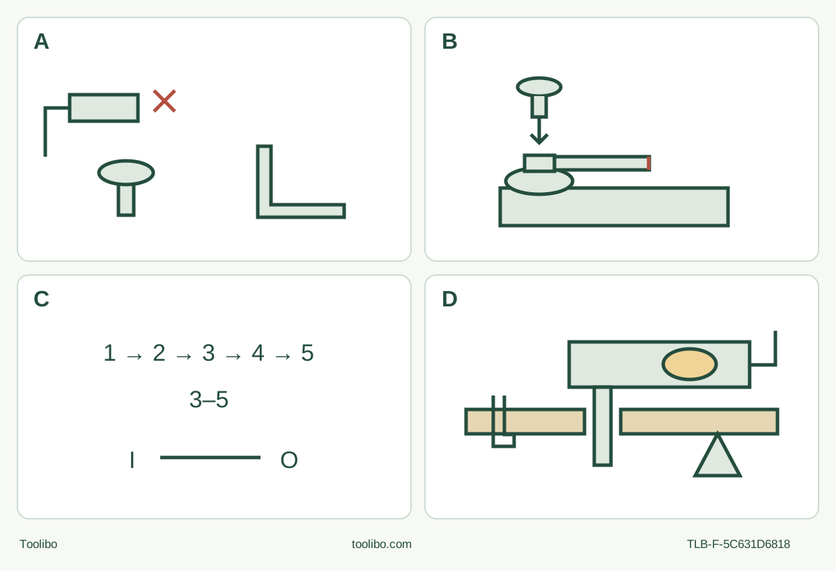
A · Isolate and retain the original parts
OFF, full stop and unplug before using the hex wrench to remove the original bolt and old accessory.
B · Seat the native blade fully
Fully seat all matching flange protrusions in their corresponding holes, tighten the original bolt firmly, remove the key and check while isolated.
C · Use the actual controls
Dial 1–5 through intermediate positions; cutting guidance 3–5. I starts and O stops, with no borrowed trigger or lever controls.
D · Stop before withdrawing
Use the actual barrel grip and complete supported separation. Switch OFF and wait for full blade stop before withdrawal, setdown and unplugged inspection.
Original conceptual schematic. B is not a pin-count or approved generic interface drawing. C requires passing the intermediate dial positions, not wrapping through an endpoint. D is a workholding and clearance cue, not a running depth gauge or finish guarantee.
A discontinued US body, not its replacement model
This guide is for an existing US Makita TM3000C matching the 885123-940 / TM3000C-1 instruction manual linked from the discontinued TM3000CX5 product page. CX5 describes the historical kit, not a second mechanical body. The page’s replacement-model listing does not make that replacement’s tool-less mounting instructions applicable to this screw-mounted tool. Match the actual nameplate, supplied document and controls before proceeding.
The project ends with a short, complete separating cut in dry, untreated, uncoated loose softwood, followed by isolated acceptance. Both faces and the blade exit are visible. It does not involve installed trim, hidden cables, plumbing, structural alterations or cutting a workpiece held in your hand.
The exact historical US flyer identifies original A-95255. The matched 2016 US accessory table supports that same part for plunge cutting wood and cutting wooden components. Positively identify the actual original blade, its intended material, sound condition and usable reach. Do not substitute a current replacement number, infer compatibility from the outline alone or use the conflicting width descriptions as a cutting-capacity rating. An unidentified blade means hold the project, not try it briefly.
Prepare the supply, stock and dust controls
The US flyer gives 120 V and 3.0 A. Confirm the actual nameplate and available supply agree; the operating manual’s multi-voltage extension table does not make this a dual-voltage tool. Inspect the disconnected plug, lead, housing, insulated barrel, switch, flange and original bolt. Cracks, loose or damaged hardware, an unreliable switch or an unexplained condition require qualified correction before use. Double insulation is not permission to use damaged wiring or modify the plug.
Prefer a suitable accessible supply without an unnecessary extension. If an extension is required, its condition and rating must satisfy the exact manual’s table for the actual current and complete cable length, as well as its own instructions. Never guess a gauge or pool the table’s voltage rows. Keep the cord outside the entire blade route, away from heat, sharp edges and moving parts, and arranged against snagging or tripping. Plug changes, cable replacement and internal electrical work are not part of this project.
Use a dry, stable, well-lit work area away from explosive or flammable atmospheres. Keep bystanders clear. Inspect the entire stock and marked cut route for nails, screws, staples and embedded debris; exclude unknown coatings, treated wood, wet material and unidentified dust hazards. Clamp the retained portion to a stable platform. Independently support the waste so that it can separate without closing the kerf on the blade. Check that clamps, supports and the bench are outside the full oscillating envelope and below-face exit space. Hands and your body are not workholding devices.
Wear proper safety glasses or goggles, not ordinary spectacles, and hearing protection appropriate to the work. The manual requires a correct dust mask or respirator for the material and application; ventilation does not replace that requirement. Follow the material safety information and control exposure for nearby people as well. Before connecting or checking dust equipment, switch the tool OFF, wait for complete stop and unplug it; isolate the extractor under its own instructions as well. Where dust collection is provided, connect and use it correctly under its actual instructions, then operate and check the qualified system before cutting. Do not claim the optional sanding extraction assembly captures saw-blade dust. If the actual dust controls cannot be qualified, stop rather than creating a dusty trial to judge them.
Install the original blade with the cord disconnected
Slide the switch to O (OFF), wait for complete standstill and unplug. Keep control of the disconnected plug. Allow a previously used accessory to cool, and use suitable protective gloves for handling its sharp or hot edges. Gloves must never become a reason to reach near moving parts.
Using the original suitable hex wrench, loosen and remove the application-tool installation bolt, then remove the old accessory. This is not a lever-release or spring-pin operation. Inspect the mating surfaces and original hardware; remove accessible loose debris without altering the flange or grinding a blade to fit. Persistent damage, contamination or incomplete identification is a service or documentation hold.
Place the correctly oriented native blade on the flange so that all matching flange protrusions are fully seated in their corresponding accessory holes. Do not install the blade upside down. The manual permits accessory orientations in 30-degree increments; this is an orientation choice, not a bolt-tightening angle. Keep the blade and intended working direction consistent with the actual source drawing and the clear cut route.
Fit the original installation bolt and tighten it firmly with the hex wrench, as specified. Do not add a guessed torque, extra washer, adapter or another model’s bolt. Remove the wrench before power can be connected. Check secure seating while isolated. If the accessory rocks, sits unevenly or remains loose, do not energise it to see whether it settles. An attachment that can physically be mounted is not automatically one Makita recommends for this body and material.
Check the complete blade for cracks, breakage, bending, wear and dullness. With the tool still unplugged, compare the actual usable blade reach and full oscillating clearance with the sample. There must be clear space for complete breakthrough and for withdrawing the stopped blade without striking a support. Do not turn the supported wood into an improvised depth gauge while the tool runs.
Set the dial without forcing it across its ends
The manual gives a 1–5 speed dial and a total no-load range of 6,000–20,000 oscillations per minute. It recommends presetting 3–5 before cutting. There is no exact intermediate dial-to-speed table or universal wood setting here. Use the documented cutting range and the actual known material, rather than copying a different Makita model’s controls.
The dial cannot be turned directly from 1 to 5 or from 5 to 1 across the end stop. Move through the intermediate numbers; forcing the end stop can damage the tool. Preset while OFF and unplugged. Electronic constant-speed control is not an overload licence, a guarantee of finish or a substitute for light feed.
Before connecting the supply, verify OFF, secure accessory, removed wrench, sound clamps, independent waste support, cord clearance and operating dust arrangements. Establish stable footing and a firm grip on the actual insulated barrel shown in the manual’s cutting illustration. This is not a borrowed two-handle template. Keep the other hand, your face and body outside the application tool and its path; do not reach underneath the stock.
Cut, stop fully, then withdraw
Hold the blade clear of the stock before sliding the switch to I (ON). Establish controlled running, then bring the accessory into the marked cut. Move forward with feed light enough that the accessory movement does not slow down. Do not force the tool, twist the blade to steer a corner or lever the waste free. Excessive load can lock the motor and stop the tool; it is not a normal way to regulate the cut.
Keep the whole cut visible and maintain support until complete separation. If the sample shifts, the waste begins trapping the blade, visibility is lost or the tool behaves unexpectedly, stop the operation. Do not reposition the stock or clear waste around a moving blade. An unexplained stall or electrical symptom needs isolated assessment and, where unresolved, qualified service rather than repeated powered trials.
The stopping order is important: switch OFF and wait for the blade to stop completely before withdrawing it from the workpiece. The exact manual states this requirement. After full stop, withdraw along the clear path, set the tool down safely and unplug before touching the blade or inspecting the sample. Do not carry a running tool at your side or leave it running unattended. Avoid unnecessary no-load operation.
Make an isolated acceptance decision
After unplugging and allowing hot parts to cool, inspect both faces and the entire separated edge. Accept the sample only if it is fully cut through along the intended line and size, without uncontrolled tear-out, scorching, shifted workholding or marks showing a support trapped the blade. This is a practical sample decision, not an invented dimensional tolerance or a guarantee of a finished joinery surface.
If the result is poor, stop and identify a documented correction: a sound, positively identified original blade, a clearer approach or improved workholding and dust control. If the holder, bolt, switch, supply or blade identity remains uncertain, obtain qualified help before another cut. A short successful sample does not certify hidden electrical or mechanical condition. Deal with splinters only as a separate isolated finishing task.
Keep extraction and maintenance within their actual scope
A later sanding setup requires a fresh OFF, full-stop and unplugging sequence. Allow the old accessory to cool, wear protective gloves and use the native hex wrench to remove the original installation bolt and old blade. Inspect the actual sanding pad for cracks or breakage; do not install a damaged pad. The optional assembly shown in the manual comprises the joint, dust nozzle and dust attachment; the nozzle band’s protrusions engage the tool’s matching holes. The felt ring and sanding pad then fit onto the dust attachment and are secured with the original installation bolt. Tighten it firmly with the hex wrench, check secure seating while isolated and remove the wrench before any later power reconnection. Align the sanding-sheet holes, use a sound appropriate sheet and connect the actual vacuum hose. Do not reuse a sheet used on metal for wood. This exact sequence is not a generic hood recipe and does not establish cutting capture.
Clean and store the isolated tool without liquid ingress or solvents that can damage plastic. Keep the lead and sharp accessories protected. Carbon-brush inspection or replacement, internal repairs and adjustments belong to Makita authorised or factory service using the correct parts. Retain the exact model, nameplate and document revision for that handoff; an old warranty paragraph is not a current coverage promise.
Source basis: TM3000C Instruction Manual 885123-940, English pages 1–8 and back page 28; exact discontinued US TM3000CX5 product and linked flyer NTF-0312-2 / MA-1038-12; Makita 2016 US catalog, accessory table page 123 only.
Models referenced