
Retain, seat, close fully and inspect
A shows an isolated cord and exact document gate. B is a conceptual open-slot blade beside the retained-pin holder, with no counted engagement geometry or pin-removal arrow. C separates the locking-click/full-home requirement from the non-6 sample and Auto-sense6 distinction. D shows a retained clamp, independent waste support and clear cut envelope, not a grip diagram.
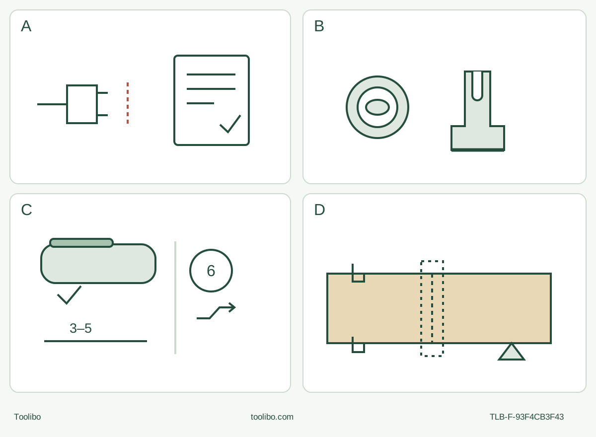
A · Isolate the matched corded system
OFF/full stop/unplug; match K4MT-03/AS21726 and original H, then qualify actual supply, PPE and dust equipment.
B · Keep the native pin
About150° counterclockwise to unlocking click; remove old open-slot blade, clean and seat all matching grooves with pin retained. No backwards blade.
C · Close and choose deliberately
Clockwise to locking click AND home, then isolated secure-pin check. Use a qualified fixed non-6 sample setting;6 has lower no-load Auto-sense behavior.
D · Complete and accept
Clamp retained stock, support waste independently and keep the full envelope clear. Controlled cut, chosen full-stop withdrawal, unplug/cool and both-face acceptance.
Original schematic, not scale or exact interface geometry. B requires all matching grooves/protrusions and the original pin to remain secured; it does not approve optional accessories. C requires clockwise closure through the click and fully home, not just a click. D promises no cutting depth or extraction performance.
Start with the actual corded body and original wood blade
This project makes a short straight separation in known, dry, clean, uncoated loose softwood. It is not an installed-floor or wall cut. Match the actual KOBALT K4MT-03, item 3735197, to its supplied AS21726 instructions and nameplate: 120 V AC, 60 Hz, 4 A. The manual recommends 5–40 °C for both operation and storage. A similar blue housing, another Kobalt model or an assortment of loose accessories does not establish this identity.
Use the positively identified original H wood plunge blade, pictured on page 3 and described in the first cutting row on page 12. H is the wood blade here; I is the separate wood-and-metal blade. The 1¼-inch description is not a promised cutting depth. Confirm the actual blade’s intended material, compatibility, condition and usable reach for the whole cut before proceeding. Missing identity, inadequate reach or uncertain hardware means HOLD, not a trial to see whether it fits. Do not substitute another model’s H accessory by letter alone.
The completed outcome is a separated sample with both faces inspectable, no remaining bridge and an acceptable marked edge. No dimensions in this project are manufacturer capacity ratings. Choose a sample and short cut that the actual tool, blade, support and dust system can complete without reaching into a hidden space.
Qualify the person, supply and fixture
Read the actual safety instructions first. Work alert, with stable footing, good lighting and bystanders clear, in a dry area without flammable or explosive atmospheres. Inspect the isolated housing, grip, switch, lever, locking pin, cord and plug. Damage, missing parts, an unreliable OFF control or unexplained looseness requires qualified correction before connection. Do not repair a cable, modify a plug or use power as a fault test.
Use an intact original cord and an appropriate matching supply. This sample assumes a suitable direct outlet; it does not supply an extension-cord sizing or electrical-conversion recipe. Route the cord away from the blade, cut exit, hot or sharp edges and walking route. Keep the vents unobstructed. The work light illuminates when the switch is ON; it is not an isolation or safe-to-handle indicator.
Wear ANSI Z87.1 safety goggles or glasses with side shields, a full face shield when needed, hearing protection and protective gloves. Gloves also apply during blade changes; they do not make contact with moving teeth safe. Use ventilation and an appropriate approved dust mask for the material. The manual’s dust precautions require extraction when connectable as well as a mask for harmful, combustible or explosive dust; this does not permit work in an explosive atmosphere. This wood project excludes unknown coatings and contamination.
Do not invent a native saw-blade dust port: the product lists no dust extraction feature. Establish a task-appropriate dust-control arrangement under the actual equipment instructions, or HOLD the work. A nearby hose is not evidence of effective collection. Before connecting or adjusting equipment, switch OFF, wait for standstill and unplug the tool; isolate the extractor under its own instructions. Any required extraction must then be correctly connected, operated and checked under those instructions before cutting. A small sample is not a dust-control exemption.
Inspect both faces and the entire cut route for nails, screws and foreign material. Clamp the retained stock to a stable bench; support the waste independently so it cannot fall, close the kerf or restrain the intended separation. Neither hand holds the stock. Establish clearance for the entire moving blade, its exit, the tool body, the slow rear-body movement, cord and any dust equipment. If the support itself occupies that envelope, change the fixture before power, not during the cut.
Change the native open-slot blade without removing the pin
Pull the switch backward to OFF, wait for complete standstill and unplug. Allow the old accessory to cool and wear protective gloves. Keep the locking pin from facing the ground during removal so the accessory cannot unexpectedly fall.
For this original open-slot route, turn the clamping lever counterclockwise about 150° to the unlocking click. Remove the old blade from the unlocked holder without stacking another blade over it. Retain the original locking pin in the drive shaft. Clean the pin and shaft; inspect the blade for cracks, deformation, bluntness or other damage and reject a suspect blade.
Place the original H blade onto the shaft with all matching grooves aligned with the shaft protrusions. Position its cutting end away from the user’s hand, never backward toward the grip. The manual permits accessory orientations in 30° increments, but that is not approval of every orientation for this fixture. Select the unobstructed forward route for this sample.
Hold the lever securely and turn it clockwise to the locking click, then continue back to its original home position. Keep fingers out of both pinch zones: lever/body and locking pin/shaft. Before each use verify the pin is fully secured and the accessory is correctly seated and retained while still unplugged. A click alone does not replace the full home position or this inspection.
The manual’s optional STARLOCK procedure removes and reinstalls the pin; it is not the native route just described. No optional accessory conversion is included here. If the pin has been removed accidentally, is loose or cannot be positively qualified, stop for the exact original instructions and qualified correction. Do not borrow another Kobalt model’s mandatory rod-removal sequence or add washers.
Choose a fixed setting and understand setting 6
Page 12 gives the original H blade a softwood range of 3–6. Page 14 calls for medium or maximum speed for initial plunge, while page 8 calls for a scrap trial to determine a suitable setting. For this project, choose a suitable fixed, non-6 setting within the supported range and initial-entry guidance, on an equally supported and dust-qualified piece of the same wood. This is an editorial choice to keep the sample outside Auto-sense, not a universal numbered cutting recipe.
Setting 6 is Auto-sense: the tool starts at a lower no-load speed and increases speed when the blade receives force feedback from the work. That does not mean constant maximum speed, permission to push harder or a mode that must be tested by forcing a blade. The published 11,000–18,000 OPM range is not an intermediate dial calibration.
The manual allows speed changes when OFF or running at no load. Here, make adjustments only after OFF, standstill and unplugging as a conservative project rule; do not describe that choice as a prohibition on the manual’s no-load adjustment option.
Make the cut, then decide whether to accept it
Recheck the secure holder, fixture, dust controls, clear blade and OFF switch before connecting power. Hold the actual insulated barrel grip shown in Figure 5a, with the free hand away from the blade and workpiece, and keep vents and cord clear. Push the switch forward to ON with the blade clear, establish controlled running, then approach the marked cut. Do not direct the blade toward your hand or use your free hand underneath the stock.
Let the blade work without forcing. With its teeth in the work, the manual permits a slow sideways movement of the back of the tool to help the cut. This is not permission to twist a trapped blade or sweep outside the qualified clearance. If the stock moves, the kerf closes, the holder loosens, vibration or noise becomes abnormal or the tool overheats, stop and isolate; do not reproduce the fault under power.
After complete separation, slide backward to OFF and wait for full standstill before withdrawal along the clear path. That stop-before-withdrawal order is a conservative sequence chosen for this project; the manual expressly requires full stop before laying the tool down. Set it down safely, unplug and allow blade and workpiece to cool before handling sharp edges or inspecting the result.
Check both faces for full breakthrough and the intended line and size. Accept only a complete separation without uncontrolled tear-out, scorching, damaged retained material or evidence of shifted support. Reject an incomplete or uncontrolled result and correct the isolated setup before another sample; never pry a remaining bridge with the blade. No numerical finish tolerance is implied.
Keep care separate from repair
With the plug removed, keep the tool and vents clean using only a soft, dry cloth; the manual says never detergent or alcohol. Maintenance belongs to qualified service personnel. Persistent poor retention, abnormal operation or uncertain original parts requires a documented service handoff, not an energized seating test or improvised tightening.
The evidence for this route is the matched AS21726 manual: identity and original H on pages 1–3, safety 4–7, controls 8–9, native mounting 9–11, material row 12, plunge guidance 14 and care 16. Sanding, scraping, optional interface conversion and other materials are separate qualifications, not additional completed tasks in this article.
Models referenced