
Sleeve, shaft, modes and supported work
A shows disconnected power, raised lever, sleeve opening and removed shaft. B shows a neutral seated accessory and shaft insertion, then closed-padlock alignment before lever lowering. C contrasts standard 1–5 and conditional AUTO frequencies. D shows retained stock clamped, independent waste support and isolation before acceptance.
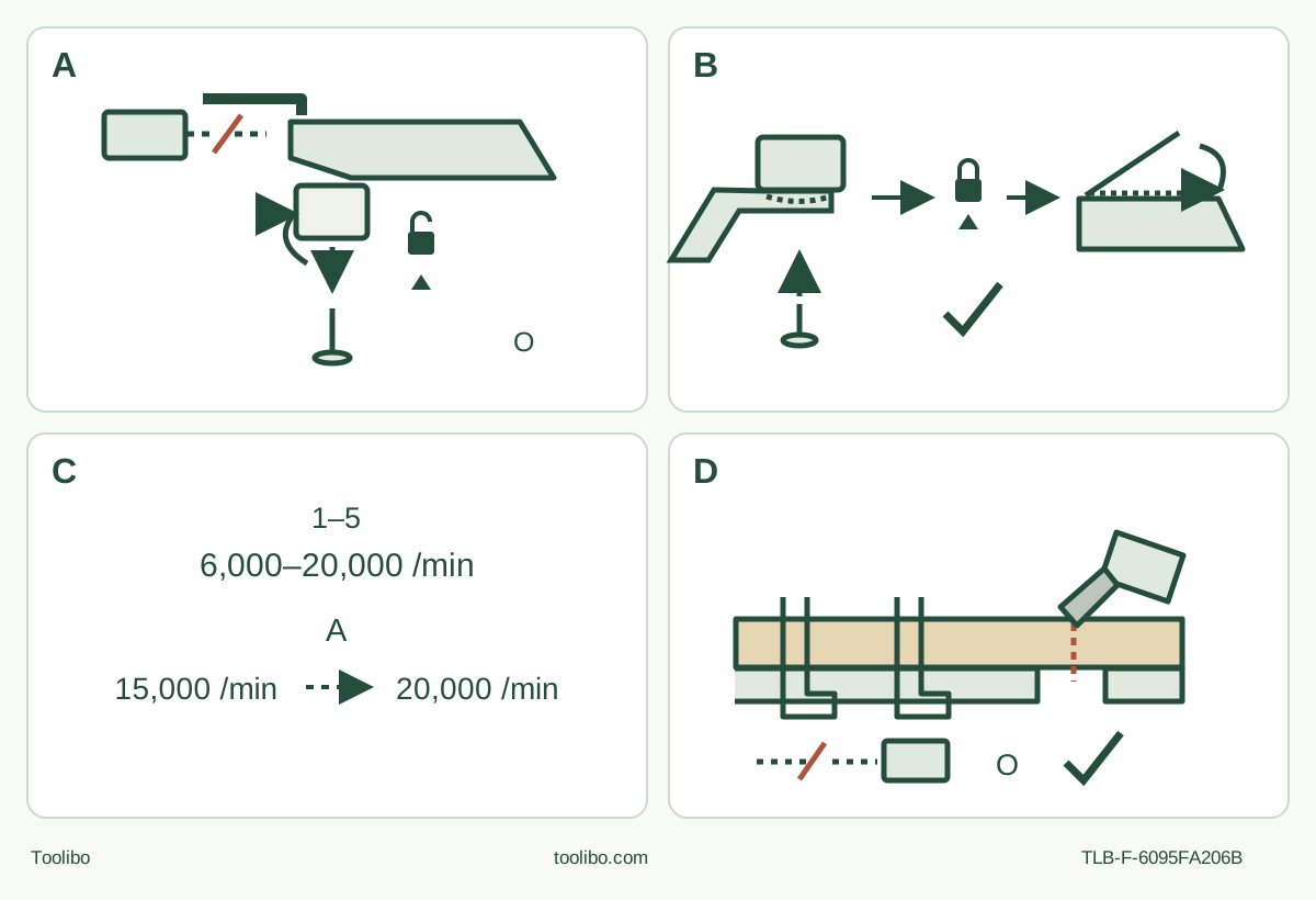
A · Isolate and open
OFF and battery removed, cool the accessory, raise the lever parallel and align the sleeve with the open lock before withdrawing the shaft.
B · Seat and close in order
Engage the actual ring, insert the shaft, align the closed lock and only then lower the lever. Verify retention without power.
C · Choose rather than assume
Standard mode is deliberately selected for this sample. AUTO values are conditional, not a diagnostic test or permission to force a cut.
D · Accept with the pack removed
Support both portions without trapping waste. Complete the cut, stop fully and remove the battery before checking line, separation and damage.
Original schematic. A and B do not establish sleeve turn degrees, pin count or an interchangeable mount. Seat the actual ring correctly, insert the shaft and align the closed lock before lowering the lever; never lower it unlocked. C shows nominal AUTO values, not guaranteed transitions or a safe force limit. D supplies no rated depth or grip position; follow the actual housing-grip figure and check the whole blade envelope.
A Canadian owner route with a specific older manual
The outcome is one controlled, visible edge cut in loose, new, uncoated softwood, followed by battery-out inspection. It is not a cut into installed trim, a wall, an unknown board or a structural member. The interesting part of this CV18DBL is the complete sleeve-and-shaft locking sequence: lowering the lever alone does not prove that the attachment is secured.
Match the actual Canadian body and supplied instructions before starting. The current Canadian CV18DBLQ5 page leads to the manufacturer’s manual-search service. Its Q5 result links the Hitachi-branded C99712063 G, with a June 2015 layout and explicit USA/Canada scope. A separate Q4 result links a later Metabo HPT document. This guide deliberately follows the Q5-linked 2015 document, not a mixture of their contents. If your actual tool, labels, locking mechanism or supplied instructions do not match, obtain the correct manufacturer guidance instead of proceeding. Packaging suffixes do not create another body count.
The source specifies an 18 V tool. Its angle row contains inconsistent wording, so this project does not use an inferred angle or clearance calculation. Product prose sometimes calls the motion RPM; the manual describes oscillation frequency, not rotation.
Start with an already qualified power system
This document’s specific power instructions identify the original BSL1850 battery and UC18YFSL charger. Use only an already commissioned, undamaged system matching those identifiers and its complete actual instructions. The charger has a 120 V supply requirement. Current product marketing and optional lists mention other packs and chargers, but those lists are not permission to replace this manual’s narrow system or improvise a new pairing. No battery or charger is promised as included, and this guide is not a charging lesson.
Do not use a damaged or deformed pack, or a charger that has been dropped, struck sharply or otherwise damaged. Leakage, abnormal smell, heat, discoloration or deformation stops the project; follow the actual safe-disposition instructions and qualified service, without opening, repairing or testing a suspect pack. Protect terminals from conductive debris and loose metal. Keep storage below 40°C and follow the actual battery instructions; a tool-mounted gauge does not establish battery health or usable capacity.
Check that the slide switch is OFF before inserting a battery. The manual expressly warns that insertion with the switch ON starts the tool immediately. OFF is still not isolation: remove the pack for attachment work, setup changes and inspection. Hold the tool securely, press the actual battery latch and pull the pack out along its rails. Do not borrow another model’s upward-removal gesture. For insertion, observe the correct orientation, seat fully and confirm secure retention.
With OFF and the battery removed, inspect the housing and handle, switch, lever, sleeve, shaft, ring and accessible original fasteners. Cracked housing or handle, damaged or loose hardware, unreliable control or any unexplained condition holds the project for qualified correction, not a powered test. Work in good light with stable footing and keep bystanders clear.
Identify the blade and make a feasible cut plan
The selected manual names the original MD28PB, code 335881 cut-saw blade; the current Canadian product identifies 335881 as a wood/metal blade. This project uses that positively identified original blade on clean softwood only. It does not expand to every accessory advertised as universal, another brand’s holder tier, or unidentified blades from a used kit. If identity, material suitability, reach or condition is uncertain, hold the task and obtain exact evidence.
Inspect the blade for cracks, damage, bending and excessive wear. Keep it sharp and clean; a dull or damaged accessory reduces cutting efficiency and can overload the motor. Check the actual mounted reach and full oscillating envelope, not just the loose blade’s apparent length. Neither the source name nor the drawing supplies a guaranteed depth for your stock.
Inspect all faces and the intended route for nails, screws, contaminants and other foreign material. Mark a short straight cut from an accessible outer edge. Clamp the retained portion to a stable platform, independently support the waste and leave the complete blade path clear above and below. The waste must be able to separate without closing the kerf or dropping onto the blade. Never hold the stock against your body or reach underneath to catch it. If that support and visibility cannot be achieved, choose another sample or another method.
Battery out: open the sleeve, seat the blade, lock the sleeve
Switch OFF, wait for complete stop and remove the battery. Let the accessory and metal holder cool. Use protective gloves for handling sharp accessories, keep fingers away from edges, and keep hands out of the spring-loaded lever’s pinch area.
Raise the lever against its resistance until it lies parallel with the main body. Pull and turn the guide sleeve to align the triangle reference with the open-padlock position. Pull out the tool shaft, then remove the old accessory if present. Do not treat the sleeve as an ordinary threaded accessory screw or invent a number of turns.
Place the correctly facing blade on the attachment ring so its mounting holes engage the ring’s protrusions. The manual permits attachment orientation in 30-degree increments; select only an orientation that preserves the checked grip, support and cutting clearance. No pin count or universal mounting approval is inferred from the schematic.
Insert the tool shaft. Bring the sleeve’s closed-padlock mark into alignment with the triangle reference, and only then lower the lever carefully. The source explicitly crosses out lowering the lever while the sleeve remains unlocked. Confirm that the correct accessory is evenly seated and securely retained while the battery is still removed. Do not add washers, substitute a shaft, guess torque or run the tool to test seating. Refit a loose or uneven accessory using the complete documented sequence; persistent failure requires qualified service.
Understand standard mode, AUTO and the two-lamp indication
Sliding toward I starts the tool and its LED; sliding toward O stops it. Do not look directly into the LED. A lit lamp is not proof of a secure clamp, and darkness is not proof that the battery is removed.
Standard dial positions 1–5 cover 6,000–20,000 oscillations per minute. The manual does not assign a precise frequency to every intermediate number. AUTO position A nominally changes between 15,000 without load and 20,000 under load, but the source warns that it may not reach the higher frequency or return to the lower one, depending on the work and attachment. It is not a force limiter, a clearance check or permission to keep pushing a stalled cut.
For this short sample, use standard mode so the chosen setting is deliberate rather than an assumed AUTO response. Select a suitable frequency for the actual material and blade on a similarly supported spare piece; no universal wood number is supplied here. Start clear of the work, adjust only with secure control and the accessory clear, and allow the selected motion to establish before contact.
Pressing the separate remaining-battery button lights the two-lamp indication only while it is held. Both lamps mean sufficient remaining power, one means about half, and neither means nearly empty. These are approximate indications affected by temperature and battery characteristics, not a runtime, capacity or fault diagnosis. Do not confuse them with the work LED or charger pilot lamp.
Complete the cut and make an acceptance decision
Arrange ventilation and appropriate dust controls under the actual equipment instructions. Wear ANSI Z87.1 eye protection and a suitable mask or respirator; use hearing protection, particularly for extended operation as the manual requires. Keep loose clothing, hair and gloves away from moving parts. Nothing about a small sample exempts it from dust protection.
The exact safety figure requires a firm one-hand grip on the housing, away from the metal front. Use the insulated gripping surface and anticipate reaction. Keep the free hand away from the blade, cut and underside; it must not steady inadequately clamped stock. Do not transplant a front-hand position from a different tool or cover the vents.
With assembly, support and dust precautions complete, confirm OFF, insert the qualified pack and verify retention. Hold the accessory clear, start with the slide switch, establish the selected standard-mode frequency and then place the blade lightly against the marked edge. Advance at a pace that does not slow the motion. Do not force, twist in the kerf, pry off a remaining bridge or use excess pressure to compensate for a dull blade.
Stop for moving stock, binding, abnormal noise or heat, a loose-looking accessory, or lost clearance. Slide to O, wait for standstill and remove the pack before checking anything. Never reproduce an unexplained fault under power. After full separation, switch OFF, wait for complete stop, withdraw on the clear path and set the tool down securely, away from chips and sawdust that could be drawn into it. Remove the pack before inspecting either face.
Accept only complete separation on the intended line and size, with controlled support and no uncontrolled tear-out, scorching or stock shift. This is a project acceptance check, not a manufacturer dimensional tolerance. Correct a documented setup issue while isolated; unexplained tool behavior goes to qualified service. A satisfactory sample does not qualify installed or hidden-service work.
Keep protection and maintenance separate from the sample
The manual distinguishes exhausted battery output, overload shutdown and overheating under overload. Stop, switch OFF and isolate; follow the actual power-system instructions and allow cooling where required. Do not keep cycling the switch or run a suspect system as a cooling experiment. AUTO changes and a fuel indication do not identify the cause.
For care, switch OFF and remove the battery. Inspect the accessory, accessible fasteners and vents; do not invent tightening torque or dismantle the holder or motor. A soft cloth, or one lightly dampened with soapy water where permitted, can clean exterior dust; dry thoroughly and keep water or oil out of the motor. Do not use bleach, chlorine, gasoline or thinner. Internal repairs and unresolved defects belong to the manufacturer’s qualified service route.
Sanding remains a separate qualified application: the source requires the proper pad, aligned paper holes, unworn unclogged paper and no wood sanding with paper previously used on metal. This wood-cut result does not approve a sanding pad, dust attachment or scraping project.
Source basis: Canadian CV18DBLQ5 product and public manual-search result; CV18DBL C99712063 G, full English 3–19, figures 1–11 and back cover. This is a document-based matched-owner workflow, not physical testing, a current-kit guarantee or an assertion that the older document applies to every later body.
Models referenced