
Isolate, remove the flange, seat and support
A shows a disconnected cord and HE41 identity. B presents the original flange and a neutral forward blade separately, beside an open-lever cue; it is an inventory, not a dimensional assembly drawing. C shows a neutral uncounted engagement outline and closing-lever cue, followed by isolated retention. D is a plan-view cut corridor with retained-stock clamp and independent waste support.
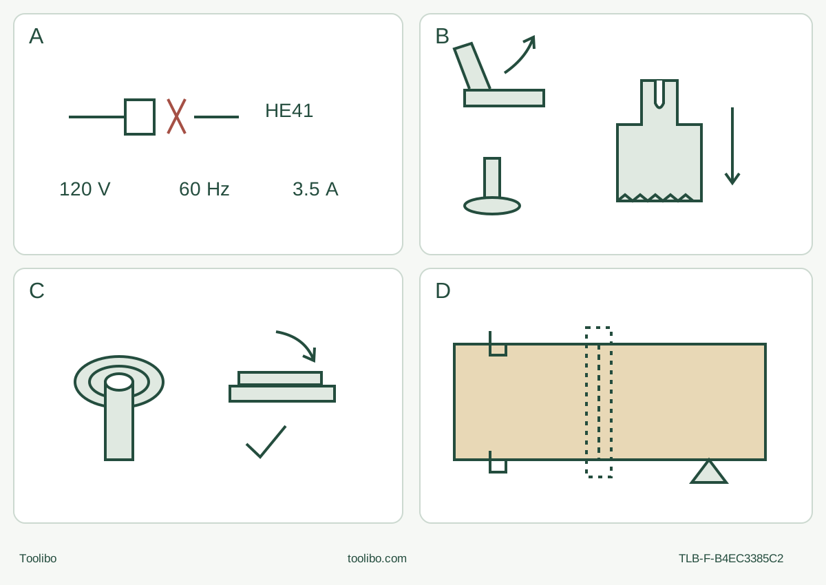
A · Match and disconnect
Confirm the exact selected UPC and original supply. OFF, full standstill and unplug before handling; another linked UPC is not interchangeable evidence.
B · Remove and retain the flange
Open the original lever and remove the original flange and cooled old accessory. The new blade is separately qualified and must face forward away from the handle.
C · Engage and close completely
All corresponding blade holes engage the fitting pins before the flange is replaced and lever closed. Check retention while unplugged; persistent movement is a service hold, not a powered test.
D · Complete a supported sample
Clamp retained wood and support waste independently without closing the kerf. Keep the full blade, hands, cord and underside clear; complete the controlled cut, full stop and isolated acceptance.
Original schematic, not scale. B and C do not supply a pin count, torque or substitute hardware. Follow the actual original lever and flange. A cutting blade faces straight ahead away from the handle; no 90-degree setting is approved. D requires full underside clearance and actual support, not a depth guarantee.
Start with the correct HE41 and a separately qualified blade
This project takes an identified HERCULES HE41 from an isolated accessory change to an accepted short cut in loose softwood. It is limited to item 59510, actual UPC 193175473134 and the matching Rev 26i owner’s manual. The current product page links more than one UPC document. A similar housing or the same item number does not establish that another version has the same parts or procedure. Match the actual nameplate, supplied instructions and original hardware first; otherwise stop for Harbor Freight clarification.
The selected body is 120 V AC, 60 Hz, 3.5 A. Its blade is not included. The separate accessory used here is an original HERCULES HA23-63, item 70251, whose product information explicitly identifies softwood and hardwood, HERCULES compatibility and a maximum of 20,000 OPM. That is evidence for this named accessory, not a promise that every blade called “universal” fits. Confirm the actual blade markings, intact mounting area, sharp undamaged teeth and suitable usable reach. A loose unidentified blade or an accessory that needs improvised hardware is not an alternative route.
The tool’s current product maximum is also 20,000 OPM. The manual’s specification says 11,000–20,000/min, while its generic symbol legend calls the unit RPM. Do not calculate a conversion or invent a dial calibration from that wording. If the actual body or accessory rating conflicts with the selected documented system, hold the project rather than assuming compatibility.
Evidence: HE41 Rev 26i cover and pages 5–6; exact HE41 product specifications; HA23-63 / 70251 product specifications.
Define an inspectable cut, not an installed repair
Choose known dry, new, untreated and uncoated loose softwood. Mark one short straight separating cut that the actual blade can complete without its holder or body striking the work. No thickness in this guide is a manufacturer capacity. Inspect both faces and the complete route for nails, screws, grit and other foreign material. Do not substitute installed trim, a wall, a pipe or wood of uncertain treatment/history.
Clamp the retained portion to a stable bench. Support the waste separately so it does not drop uncontrolled, pull the last fibres apart or close the kerf against the blade. The support must not turn the waste into a rigidly restrained second side that pinches the cut. With power disconnected, check the complete oscillating blade envelope, breakthrough space underneath, body clearance, both gripping positions and all clamps. If you cannot maintain support and see a clear exit, change the setup before cutting or choose another qualified process.
Work in a dry, clean, well-lit area with stable footing and bystanders clear. Exclude flammable liquids, gases and explosive dust atmospheres. Route the cord with enough slack to move freely but outside the cutting path, sharp edges and walking route. Match the intact original plug and actual nameplate to the proper supply; do not modify a plug, open the housing or attempt cord repair. This sample is planned near a suitable outlet. Any necessary extension requires the actual manual’s length/load selection and sound condition, not a borrowed gauge from another tool.
Make the protective and dust system ready
Use the manual’s ANSI-approved eye protection with side shields, hearing protection and suitable heavy-duty work gloves. Keep gloves, clothing and hair away from moving parts. Breathing protection must be NIOSH-approved for the actual dust hazard; “small sample” does not mean harmless dust. Plan ventilation and any suitable dust collection before work. Where collection facilities are provided, the manual requires them to be connected and properly used. This guide does not establish a native saw-blade hood or a numerical extractor threshold.
Before connecting or adjusting any dust equipment, switch the tool OFF, wait for complete standstill, unplug it, and isolate the extractor under its own instructions. Establish the actual suitable equipment, hose routing and unobstructed blade/hand envelope. Operate and check that equipment under its instructions before cutting. If the dust-control requirement or connection is uncertain, hold rather than relying on visible dust, sound or a light as proof of protection.
While the tool is isolated, inspect its housing, insulated gripping surfaces, switch, cord, original lever and flange, accessible hardware and blade. Cracks, loose or damaged parts, unreliable controls, unexplained vibration history or an unsuitable supply are stop conditions. A powered test is not how to establish an uncertain clamp or electrical condition.
The manual also imposes a personal-suitability gate: pregnant users and people with impaired hand circulation, past hand injuries, nervous-system disorders, diabetes or Raynaud’s disease should not use this tool. Regular or extended use requires an initial medical examination and regular follow-up checks. Pacemaker users should consult their physician before use. Tingling, numbness, white or blue fingers, or other vibration-related symptoms require medical advice; stop rather than continuing. Do not smoke during use, and include vibration-free periods. These are the manual’s screening precautions, not a medical diagnosis or treatment plan; its generic grounding and locked-switch examples do not add features or modification instructions to this body.
Evidence: HE41 Rev 26i pages 2–5 and 7.
Remove the flange, engage the pins and close the lever
Establish OFF and full standstill, then unplug before touching the accessory. Let the old blade cool and wear protective gloves for its sharp edges. Keep the disconnected plug under your control. The following is the selected manual’s native assembly, not a screw-and-key or spring-only clamp.
- Open the original release lever and remove the original flange. If an old accessory is fitted, remove it now; do not stack a new blade over it.
- Check that the original flange, spindle fitting pins and new blade mounting area are sound and free of obstructing debris. Install the selected blade with its corresponding mounting holes fully engaged on the spindle’s fitting pins.
- Replace the original flange, then close the release lever. Do not add washers, substitute a bolt, invent a tightening torque or treat a partly closed lever as finished.
- Check the secured accessory while still unplugged. It must not move on the spindle. If it moves, the manual directs reinstallation with the holes correctly aligned to the pins. Persistent movement, damage or uncertain parts means stop for qualified correction, not a harder lever push or an energized seating test.
A cutting blade must point straight ahead, away from the handle. The manual’s allowance of up to 90 degrees left or right for other accessories is not permission to angle this blade. Recheck its complete forward path against the work and supports after mounting.
The selected UPC manual says replacement parts are not available. That does not authorize substitute flange hardware or guarantee that a repair is possible. Seek the manufacturer’s qualified disposition if the original assembly cannot be established.
Evidence: HE41 Rev 26i page 6, actual accessory-installation figure.
Make the sample with two hands and a clear start
Before connection, confirm OFF, secure isolated seating, cleared tools, stable workholding, functioning dust controls and the complete cord/blade path. Grip the tool firmly with both hands on its insulated gripping surfaces, without covering ventilation ducts. Keep hands away from the cutting end and underside; do not use one hand to catch waste. The own-cord warning and controlled loose-stock project are not permission to cut hidden services.
Use the speed dial and a properly supported scrap of the same known material to establish a suitable setting. The manual gives no numbered wood recipe. With the accessory clear of the wood, slide the power switch forward to ON and let the tool come up to the intended speed before contact. Apply light controlled pressure and let the blade cut; do not force it, pry with it or twist it to turn the straight path into a curve. Keep both grips, support and cord clearance throughout separation.
If the work shifts, the blade binds, the accessory moves, or unusual noise or vibration appears, stop and isolate. Do not repeat the event to diagnose it. If a documented isolated setup correction cannot explain and resolve the condition, send it for qualified service. Include vibration-free breaks; stop for symptoms rather than pushing through them.
For this project, the conservative completion sequence is to slide the switch to OFF, hold control until complete standstill, and only then withdraw the blade along the clear route and set the tool down securely. This chosen withdrawal order is not presented as a special quoted OEM rule. The manual expressly requires full stop before setdown and OFF/unplugging after use. Unplug before inspecting the sample or touching the attachment.
Accept the result or stop the next cut
Allow the blade and cut edges to cool and keep clear of sharp teeth and splinters. Inspect both faces: the cut must follow the intended line and separate fully without a hidden bridge, uncontrolled breakout, scorching or evidence that the clamps/support shifted. No numerical finish tolerance is invented. If the result is not acceptable, do not simply repeat the same setup; correct an established material, support or feed issue while isolated, or seek qualified advice.
Wipe external tool surfaces with a clean cloth and store the dry disconnected tool and protected blade out of children’s reach. Internal work, damaged cord/plug replacement and procedures not explained in the manual belong to a qualified technician. Generic troubleshooting mentions of a reset breaker “if equipped” and malformed locked-switch wording do not establish a reset button, lock mode or restart-protection feature on this body. The useful finish is a sound sample and a known isolated system—not an improvised repair.
Evidence: HE41 Rev 26i pages 3, 6–7; the sample acceptance criteria are project checks, not manufacturer performance guarantees.
Models referenced