
Isolation, two clicks and a complete sample
A shows a removed battery and OFF. B separates closed-lever confirmation from a downward machine-to-accessory engagement arrow, with neutral uncounted seating planes. C distinguishes the two adapter screws and 7 Nm from a crossed-out transfer to the blade holder. D shows retained wood clamped and waste independently supported outside the full cut path.
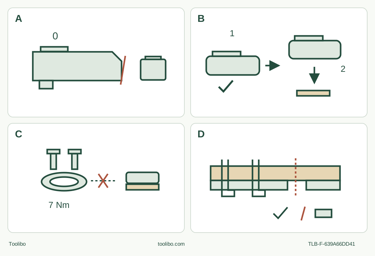
A · Isolate
Set 0, wait for standstill and remove the battery before changes. Match the actual commissioned BP 18 system.
B · Close, then press
Remove the old blade safely, close the lever to its click, then press the device onto the original accessory to the second click. Check seating while isolated.
C · Keep torque in its place
The two adapter screws use 7 Nm; the native blade holder has no invented tightening torque. Complete actual extraction assembly and equipment qualification.
D · Support and accept
Clamp the retained portion, support waste independently and check full reach and sweep. Stop, remove the pack and inspect both faces after separation.
Original conceptual schematic, not an exploded parts drawing or a complete extraction assembly. B requires the lever click before pressing the machine onto the original blade; it does not specify jaw shape or pin count. C marks adapter-only torque; follow actual Figures 5–6 and the extractor instructions for full assembly. D is a support plan, not a depth rating or operating grip diagram.
A complete US owner cut starts with two different clicks
Complete one short edge-entry separation in known, new, uncoated loose wood, then inspect both faces with the battery removed. The OSC 18’s first click closes the clamping lever; the second secures the original accessory when the machine is pressed onto it. Neither sound alone proves that the whole work, power and dust system is ready.
This guide uses the current US OSC 18 E-Basic product identity and operating manual 718544_J, 2024-03-05. The selected original blade is USB 78/32/Bi/OSC, with the same blade identified as USB 78/32/Bi/OSC/5, order 203337, in the accessory evidence. The /5 denotes a pack quantity, not a different tool. Actual body, blade, markings and supplied instructions must match; no current kit-in-hand or stock promise is made.
The 2022 accessory catalog’s universal bi-metal group expressly includes wood. Its exact row gives 78 mm length and 32 mm width, but does not carry the strongest-suitability dot in the solid-wood column. This is therefore a bounded wood-use route, not a claim that this blade is the best solid-wood choice. Those dimensions are not an installed cutting-depth rating. The catalog supplements blade identity and material evidence; it does not replace the US operating instructions or approve another regional power system.
Establish a sound, already commissioned system
The body is an 18 V cordless machine using the specified Festool BP 18 system. Begin only with an original, already commissioned compatible pack and manufacturer-specified charger, whose own instructions the owner has read and matched. This article supplies no named charger, charging-light sequence or temperature recipe. Do not use third-party chargers, a mains power unit or a battery adapter. If the actual power qualification is missing, stop before this project rather than infer compatibility from voltage alone.
Set the switch to 0 and wait for complete standstill; press the actual battery release button [1-7] and slide the pack fully out as Figure 2b shows before inspection or any adjustment. Check the housing, gripping surfaces, switch, lever, holder, battery interface and accessory for damage, contamination, missing parts or unexplained looseness. Do not use a damaged or modified battery or tool. An unreliable switch or unresolved condition needs qualified service, not an energized test. Keep the interface clean; a poor contact can overheat or damage the machine.
Work in dry, weather-protected surroundings with stable footing, good light and bystanders clear. Keep handles clean and dry, and clothing and hair away from movement. Use protective goggles, hearing protection and the specified P2 respiratory protection for dust, together with ventilation and appropriate extraction. Wear protective gloves for accessory changes and avoid hot or sharp edges. A small sample is not a dust-control exemption.
Decide whether the actual blade can complete the whole cut
The holder accepts the listed Starlock, StarlockPlus and StarlockMax tiers, but the manual separately requires original Festool accessories and consumables intended for this machine. Tier compatibility is not permission to use arbitrary third-party blades. Positively identify the selected original USB blade, its application and any marked maximum speed. Reject blunt, cracked, bent, broken or otherwise faulty accessories. Carefully remove protective resin from a new cutting edge as instructed, without placing fingers in the cutting path.
Inspect every face and the proposed cut for nails, screws and foreign material. Mark the retained portion and waste. Clamp retained wood to a stable platform; independently support waste so it can separate without closing the kerf or dropping onto the blade. Keep the complete underside visible. Check the actual mounted blade’s reach and full oscillating envelope against the wood, clamps, support and planned withdrawal path. Do not use the nominal 78 mm length as available depth, bend the blade or plan to snap an uncut bridge.
This is an accessible outer-edge cut, not an interior plunge, installed flooring cut or guided-fixture demonstration. If the full separation cannot be completed without striking a support or losing either grip, change the sample or method. Do not compensate with a free hand holding the stock.
Battery out: remove, close the lever, then engage
Allow the old accessory to cool, wear gloves and keep hands clear of the spring-loaded jaws. Open the clamping lever to release an old accessory; it drops down, so arrange a clear, safe receiving area without trying to catch the sharp edge. Close the lever until it clicks. Remove the old accessory from the work area before positioning the replacement.
For insertion, if the jaws are open, open and close the clamping lever as the manual directs. Close the lever until it clicks first; then push the device onto the correctly oriented accessory until that connection clicks. The accessory can be positioned in 30-degree increments, but only a position meeting the checked grip and clearance plan is acceptable. Inspect straight, secure seating while still isolated. Do not add a screw, pin, washer or clamp torque from another system.
Never reach around the jaws, actuate the lever while running or energize the machine with the lever open. The manual warns that the spring can close the lever and crush fingers. An accessory that does not seat and remain secure after the correct clean assembly is a service hold, not a reason to test it under power.
Complete the actual dust route before cutting
Only an extractor designed for the actual material’s dust is acceptable, operated under its own instructions and the applicable OSHA/NFPA requirements stated in the manual. This guide does not invent a vacuum-pressure minimum, hose equivalence or capture guarantee. If the actual extraction system cannot be established, the project is not ready to run.
If using the original tool-mounted extraction device shown in Figure 6, assemble it with the tool battery removed and the extractor isolated under its instructions. With the blade removed, fit the original adapter as Figure 5 shows, using its two screws at 7 Nm. That torque belongs to the adapter, not to the click-in blade holder. Align the extraction device’s marks with the adapter, operate the retaining tab and rotate it into its illustrated retained position; then connect the appropriate suction hose. Check retention and clearance, and install the blade through the complete isolated sequence above. Remove any assembly key before later power connection.
Operate and check the qualified extractor under its own instructions before making dust. Route the hose so it neither pulls the tool nor enters the blade or support area. Maintain both designated grips and unobstructed vents. A fitted hose alone does not establish effective collection. If airflow or retention is uncertain, stop, isolate both devices and resolve the actual equipment requirements; do not continue on the basis of sound or feel.
Deliberate start, controlled feed and isolated acceptance
The switch positions are I for ON and 0 for OFF. The speed wheel continuously adjusts within the nominal 10,000–19,500 min⁻¹ range; respect the actual accessory’s marked limit. The manual’s illustrated SPEED MAX 4 marking belongs to the depicted USB 78/42 blade. It is not a universal wood setting or an established limit for every USB 78/32. Establish the selected blade’s own restrictions before choosing a setting; no numeric wood recipe is supplied here.
Once assembly, support, extraction and power prerequisites are satisfied, confirm 0 and insert the qualified pack until it clicks. Hold the machine firmly with both hands on the designated gripping surface, not the battery, keeping cooling openings clear and your body and hands outside the operating blade and cutting path. With the blade clear of the wood, switch to I and establish the selected motion before approaching the marked edge. Feed lightly and keep the tool aligned. Increasing force and slowing progress can indicate a worn blade; do not force, twist or pry.
Stop for moving stock, lost clearance, binding, loose attachment, abnormal heat or unexplained behavior. Move to 0, wait for complete stop and remove the pack before inspection. Do not repeatedly restart to reproduce a fault. Following full separation, switch to 0, wait for standstill, withdraw along the clear path and set down securely outside trip or fall hazards. Remove the battery and allow hot parts to cool before touching the result.
Accept only a fully separated sample on the intended line and size, with stable support and no uncontrolled tear-out, scorching or stock movement. This is a project decision, not a manufacturer tolerance. Correct a documented setup issue while isolated before another sample; unresolved mechanical or control trouble belongs with qualified service. Success does not approve hidden-service or installed work.
Warning signals and care are not a restart experiment
The manual lists several states that can produce a warning and another shutdown when switched on: an unaccepted, empty, faulty or overheated pack, an overheated tool, or a tool fault. A jam shutdown may have no warning sound. Do not intentionally restart to classify the fault, infer health from silence or treat every stop as an empty battery. Move the switch to OFF immediately when power is lost or the pack is depleted. Follow the actual battery instructions, allow required cooling and use Festool service for an unresolved fault; never repair a damaged pack yourself.
For care, keep the battery removed, vents unobstructed, contacts clean and warnings readable. Avoid solvents harmful to plastics. Motor or gear housing work belongs to authorized service using original parts. The gypsum-specific compressed-air instruction is not a general wood-dust blowing mandate; positioning-aid guide oil is not lubricant for the holder or battery contacts.
The optional depth stop and positioning aid remain separate projects. The latter has its own blade-on-guide-before-holder sequence, specified blade choices and gripping surfaces; none is established merely by completing this edge cut. No app, mains adapter or guided-plunge shortcut is implied.
Source basis: OSC 18 US 718544_J, complete English pages 3–13 and actual Figures 1–6; current US product identity; exact accessory catalog 2022 printed page 089 and corroborating US part identity. This is a documented owner workflow, not hands-on testing or a current-kit guarantee.
Models referenced