
Adapter, blade sequence, guided plunge and acceptance
A shows an isolated power symbol, a neutral adapter and two original screws beside 7 Nm. B separates blade contact with a guide from later holder engagement as steps 1 and 2. C shows a vertical tool and guide columns, a depth stop, full base supported on clamped wood, safe grip highlights and an extraction hose clear of the blade. D shows a narrow slot on two faces, with no removed plug.
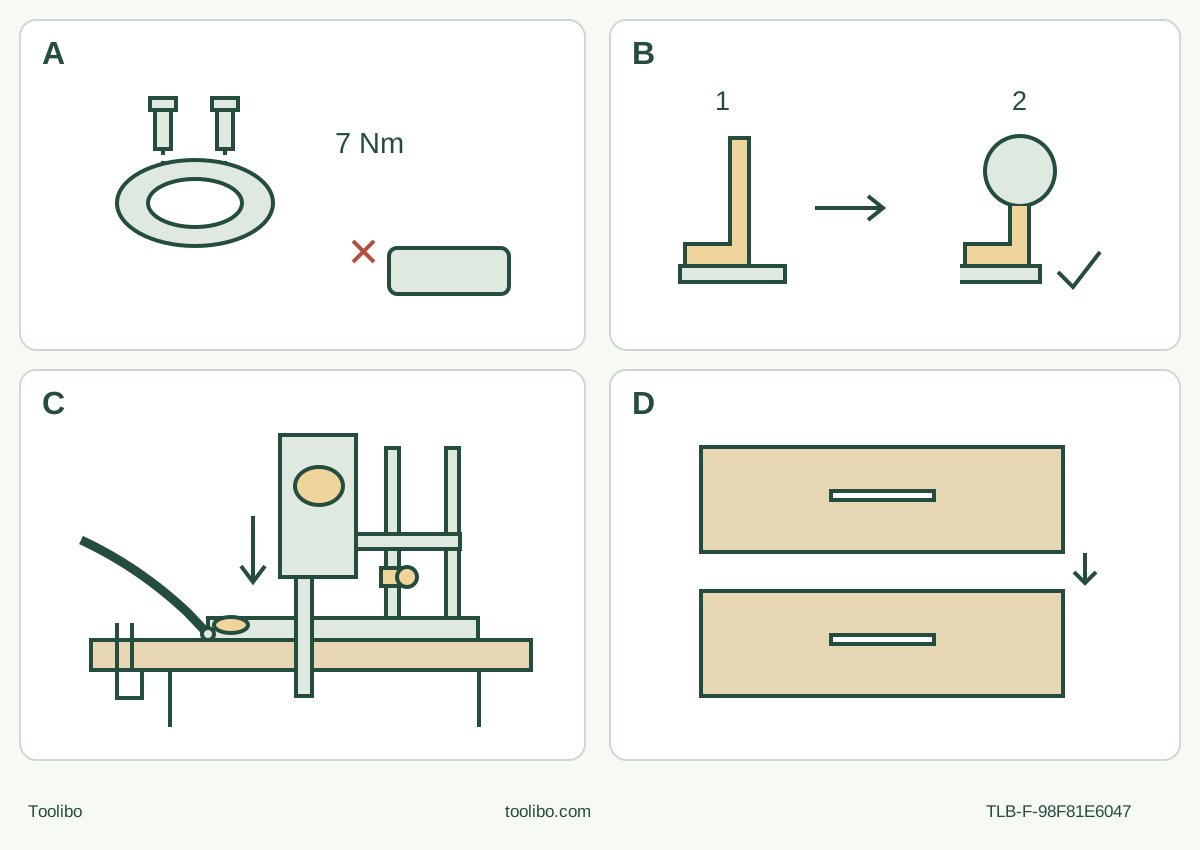
A · Isolate and mount the original adapter
Remove the pack and old cooled blade safely. Close the native lever to click. Mount OSC-A with its two original screws at 7 Nm; retain the actual OSC-AH orientation with the detent.
B · Guide before holder
Place original long USB 78/32 on the blade guide first, then engage it in the holder to click. Check alignment and secure seating without power; no short blade or forced reverse order.
C · Tighten the stop and prove the whole setup
Set actual through-travel within documented limits, tighten the stop, provide full-base support, clamped stock, complete underside/hose clearance, defined grips and qualified active extraction.
D · Inspect one finished feature
Make one perpendicular plunge without sideways sweeping. Stop fully, withdraw under control, isolate and inspect both faces for full penetration, intended position and no uncontrolled damage.
Original conceptual schematic, not a dimensioned assembly drawing. A torque belongs only to the two adapter screws. B means guide contact BEFORE holder engagement and retains the native closed-lever prerequisite. C grip highlights denote the actual tool grip and defined base finger pad, never the central moving zone; full base, complete blade travel and actual extraction must be independently qualified. D accepts only a fully penetrated single slot after stop and isolation, not a rectangular opening.
The finished feature is one slot, not a rectangular opening
This project uses the original Festool OSC-AH positioning aid 203254, original OSC-A adapter and original USB 78/32/Bi/OSC blade on the matched US OSC 18. The result is one perpendicular, depth-limited, single-plunge through-slot in a known loose piece of dry, new, uncoated wood. The stock stays intact around that narrow feature. No free plug, four-sided opening, outlet cutout, structural joint or installed-floor operation is promised.
The fixture adds a separate qualification task to the ordinary OSC 18 owner system. You need the actual US body and supplied 718544_J instructions, the complete original guide/adapter hardware matching pictorial sheet 718287_D, and a positively identified original blade. The sheet is one pictorial page, not an English instruction booklet; the full English safety and operation instructions are in the US tool manual. Some inner panel labels abbreviate OSC-AH to OS-AH. That is not permission to substitute an older OS 400 fixture.
The exact blade’s catalog group supports wood use and plunge cuts. It does not award this blade the strongest solid-wood suitability dot or guarantee the finished slot’s width. Its nominal 78 × 32 mm geometry is not installed depth or an exact cut-size specification. The positioning-aid product lists a maximum plunge depth of 1-5/8 inch (42.00 mm); treat that as a published limit to check against actual instructions, not exact unit equivalence, a default setting or proof that your stock can be penetrated safely. If the actual blade, travel, support or extraction system cannot satisfy the following gates, do not cut.
Isolate and qualify the complete system
Use only an already commissioned original BP 18 system of the correct voltage class, with the actual battery and specified manufacturer charger instructions understood. Before use, inspect the actual BP 18 and battery interface for a clean, sound condition. A damaged or modified pack, unreliable connection or contaminated contacts means hold under the actual battery/tool instructions; do not repair the pack or try a live test. This is not a charging or new-battery commissioning guide. No mains adapter or cross-brand battery is included.
Move the tool switch to 0, wait for complete standstill, press the actual battery-release button and slide the pack fully out. Isolate the extractor under its own instructions before connections or equipment adjustments. Keep this isolation throughout adapter installation, blade changes, guide correction and depth setting. Allow sharp accessories to cool and wear protective gloves when handling them. Never reach into the spring-loaded jaws or run the tool with its clamping lever open.
Inspect the tool housing, switch, jaws and lever; the original blade; both adapter screws and the detent; guide rods and contact surfaces; the depth collar/knob; base and defined finger pads; and the extraction connection. Reject damaged, bent, dull, loose, missing or unidentified parts and any unexplained resistance or unreliable locking. A fixture that does not retain correctly is a service case, not something to hold together by hand or test under power. Ensure warning labels remain legible.
The actual original OSC-AH has its own extraction connector. Obtain a documented compatible hose/coupling and an extractor suitable for the particular wood dust, with complete equipment instructions. Do not stack the separate OSC-AV on this fixture or assume another Festool hose necessarily fits. No hose diameter, connection turn angle, airflow number or capture guarantee is supplied by this article. Missing equipment identity or instructions means hold. Ventilation, protective goggles, hearing protection and the manual’s P2 respiratory protection still apply; a small sample is not an exemption.
Fit the adapter, then the guide, then the blade
Remove any existing accessory while isolated: arrange a safe receiving area for the blade, open the native clamping lever and allow the accessory to drop without putting fingers in the jaws. Close the lever until it clicks. The closed-lever state must be established before subsequent blade engagement; if the jaws were open, follow the manual’s open-and-close lever instruction rather than energising the bare holder.
Mount the original OSC-A around the native holder with its two original screws tightened to 7 Nm, using suitable torque equipment and the actual Figure 5/sheet arrangement. This value belongs to those adapter screws, not to the blade holder, guide screw or depth knob. If the correct hardware or torque setup is unavailable, stop rather than estimating by feel. Remove the adjustment key before any later power connection.
Attach the OSC-AH in one of the orientations actually shown for that fixture: align the triangular marks, operate the adapter’s detent button and rotate into the retained orientation. Confirm retention and that the chosen arrangement allows the actual blade, base, hands and hose to clear the entire planned motion. Do not substitute the separate OSC-TA depth-stop branch or stack attachments. The diagram is an orientation reference, not a licence to invent another locking action.
If this original blade is new, carefully remove the protective resin from its cutting edge while isolated and wearing protective gloves before fitting it; no solvent method is assumed. Use only the selected original long, offset USB 78/32/Bi/OSC in this project. The fixture instructions also name a different long blade, but that does not expand this article’s material or inventory scope; short blades are expressly excluded. Place the blade on the saw-blade guide first, then engage it in the native holder until it clicks. Do not clamp it first and force it under the guide afterwards. Check its seating and correct contact with the guide while still isolated.
If the blade does not sit on the guide, first check that insertion order. The manual then provides a specific isolated correction: set the depth adjustment to maximum and tighten it, loosen the identified saw-blade-guide screw, move the guide to the blade, and retighten that screw. This is guide alignment, not the chosen cutting-depth setting; do not apply the adapter’s 7 Nm to this screw. Damage, uncertainty or failure to obtain the documented alignment requires qualified service. After correction, reset and tighten the actual project stop as described next.
Prove support, travel and the selected stop before cutting
Use a loose wood sample with enough uninterrupted top face for the fixture’s full base and safe finger pads. Inspect both faces and the intended route for nails, screws, coatings, inclusions and concealed services. Mark the intended slot position. Clamp the stock securely to stable support without distorting it. Place supports and clamps outside the complete blade envelope, including breakthrough beneath the wood, and leave room for the guide columns, body and hose. Do not hold the stock by hand or place fingers beneath the cut.
With power isolated, compare the actual stock thickness, blade position, available guided travel and free underside with the desired through-slot. Establish a stop setting that permits the required penetration while keeping the whole moving blade clear of the bench, clamps and body. Tighten the actual cutting-depth adjustment. Neither the blade’s nominal length nor the product’s nominal maximum proves this geometry. If complete penetration would require lifting or tilting the base, exhausting travel, hitting support or exceeding the documented limit, choose a different sample or stop.
The guide must be able to move in the prescribed direction without forcing or binding, and the selected base orientation must allow the required two-hand control. Keep the operating hand on the designated tool grip with vents uncovered; use only the fixture’s defined base finger pads for the supporting fingers, away from the central moving, pinch and blade zones. Do not grip the battery or reach into the mechanism. If the actual hand posture cannot satisfy both the tool’s two-hand guidance requirement and the fixture’s finger-zone warning, hold the setup rather than inventing a grip.
Connect the qualified hose to the fixture’s built-in connector under the actual equipment instructions while tool and extractor remain isolated. Route it so it cannot pull the base out of position or enter the stroke. Then operate and check the actual extraction system as its instructions require before producing dust. Work in a dry, well-lit, ventilated area with secure footing, bystanders clear and no flammable atmosphere.
Make one controlled plunge and inspect both faces
Select speed under the actual blade marking and matched tool instructions; there is no universal numerical wood setting here. Confirm switch 0 before inserting the qualified BP 18 until it clicks. Establish full base support at the marked position, with the blade clear of the wood and both hands in their designated safe positions. Switch to I and establish the selected oscillation before advancing the blade along the guide into the wood.
Feed lightly and keep the base seated. Do not twist, sweep sideways, lever the blade or force it against the tightened stop. The stop limits travel; it does not measure the finished slot or authorise extra pressure. Loss of extraction, moving stock/base, binding, unusual heat, abnormal sound or unexpectedly high feed force requires 0 and complete standstill, then battery-out isolation before investigation. On power loss or an empty battery, move the switch to OFF immediately to prevent uncontrolled restarting. Do not use repeated starts to diagnose a jam.
After the intended through-slot is complete, switch to 0 and wait for actual standstill. Withdraw under control along the guide without lifting or shifting the supported base prematurely, then set the stopped assembly down securely. No automatic spring-return action is assumed. Remove the battery and allow cooling before inspection; isolate the extractor as required before disconnecting or cleaning it.
Inspect both faces. Accept only a fully penetrated single slot at the intended position, with the required project geometry and no uncontrolled tearing, scorching, base/stop movement or unintended surface marks. No numerical tolerance is guaranteed. If a bridge remains, do not pry it free or call the cut an opening. Reassess the isolated setup and its documented limits; uncertainty or a mechanical problem means hold for qualified help, not a deeper blind pass.
Clean dust from the guide and contact faces with the battery removed. The manual allows only light, regular resin-free oil on the guide rods; keep oil off gripping pads, jaws and power contacts. The sheet’s water-drop cleaning symbol does not permit immersion or wet cutting. Internal repairs belong to authorised service, and gypsum-specific compressed-air instructions are not transferred to this wood project.
Evidence used
Festool US OSC 18 operating manual 718544_J, English pages 3–13, especially Figures 5 and 9–13; complete pictorial accessory sheet 718287_D, dated 29 June 2020; current US OSC-AH 203254 product identity and instruction link; and the exact USB 78/32/Bi/OSC catalog row/group prose on printed page 089 of the 2022 English catalog. Existing US tool and same-part blade evidence is retained without expanding its limits. This article qualifies a separate fixture task, not every guided cut that could be attempted with it.
Models referenced