
Cord, closed jaws, plate size and whole-face movement
A shows a disconnected cord and the 120 V body qualification. B uses neutral closed seating planes before a downward original-plate engagement cue, without specifying jaw geometry. C distinguishes small triangular levels 4–6 from round and large triangular maximum 4. D shows clamped wood and whole-pad movement across an accessible surface.
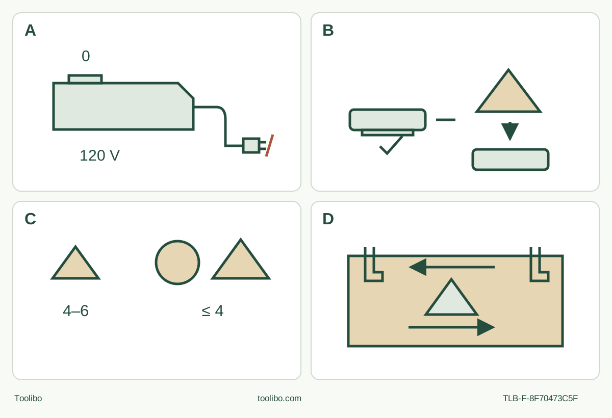
A · Unplug and qualify
Establish OFF and standstill, then unplug. Match actual 120 V supply, cord condition and the exact owner document.
B · Closed starting state
Remove the cooled old accessory safely. Close the jaws through the documented lever action, fit the original plate and check seating without power.
C · Respect plate size
Small triangular plate: 4–6. Round or large triangular plate: maximum 4. The paper-adhesion exception does not approve a powered clamp test.
D · Work the whole face
Clamp known bare wood, qualify extraction and keep the whole pad moving with moderate pressure. Stop and unplug before inspection or paper rotation.
Original conceptual schematic. A does not qualify an outlet or extension by appearance. B is not an exploded assembly or a jaw-count diagram; follow the exact original holder and extraction sequence. C is the manual’s plate-size distinction, not a universal material speed. D shows a supported surface plan, not a finish tolerance or safe hand placement.
A corded small-pad project, not a cordless substitute
Use an existing FMM350QSL, 120 V, 60 Hz USA/CAN body, matched to the May 2018 owner manual, to sand one accessible face of clamped, new, uncoated loose wood. The result is a uniformly worked intended surface without unwanted rounded edges, gouges, scorching or movement of the stock. This project does not establish a furniture-finish specification or approve painted, treated or unidentified material.
The current manufacturer service catalog identifies type 72295209360 and links owner document 3 41 01 242 21 0, May 2018. Its row is marked unavailable; no current stock or kit promise follows. Check the actual nameplate, supplied document and controls. The separate German repair document is not this owner’s authority and supplies no user repair procedure here. The 3.6 A corded body, slide switch and original clip-in holder must not inherit a cordless battery routine.
Proceed only with the actual positively identified original FEIN small triangular sanding plate, its correct original perforated wood-sanding sheet, and the matching complete native extraction assembly illustrated in the owner manual. Identify these from the actual original accessory documentation and condition, not merely a triangular outline or an advertised fitting. No pad part number or supplied grit is invented. An unidentified pad, sheet, collar, ring or retaining component is a hold until FEIN or a qualified supplier establishes the correct original set. This is an existing complete-system route, not permission to assemble miscellaneous loose parts.
Qualify the cord and dust system before setup
Set the switch OFF, wait for complete standstill and unplug before handling the accessory or inspecting the machine. Check the plug, cable, housing, gripping surfaces, switch, lever, holder and visible original parts. Damaged insulation, unreliable control, missing components or unexplained looseness requires qualified correction. Do not connect power to reproduce a fault, open the housing or substitute a cable.
Use the matching 120 V supply and actual nameplate information, with an unmodified plug and suitable outlet. The manual recommends GFCI protection rated at 30 mA or less. Keep the cord away from heat, oil, sharp edges, moving parts and the whole sanding/support area; arrange it so it cannot pull the machine or cause a trip. Work dry and weather-protected, not near flammable liquids, gases or dust.
If an extension is needed, apply the manual’s exact table with only this FMM350QSL connected. At 120 V single-phase AC, the stated minimum conductors are 16 AWG up to 100 feet, 14 AWG for the next band up to 200 feet, and 12 AWG for the next band up to 300 feet. Do not combine this with another load, infer a different-voltage approval or convert the separately printed metric bands into extra length allowance. If the actual supply or cable qualification is uncertain, stop and obtain competent assistance.
Qualify an extractor for the actual wood dust and read its own complete operating instructions. Verify the correct hose, collection arrangement and permitted operating procedure. An attached hose or a small workpiece does not demonstrate effective collection. Isolate the extractor under its own instructions whenever installing or clearing its components; unplug the multi-tool too. This article does not supply extractor electrical repair, filter servicing or invented vacuum-performance thresholds.
Wear eye and hearing protection, appropriate dust protection such as the manual’s P2-class mask, and protective gloves for all work and accessory changes. Keep gloves, clothing and hair clear of moving parts. Provide ventilation and keep bystanders away. Wood dust can burn or explode: avoid overheating the tool or material and empty the dust collector in time, following the actual extractor and material instructions. Do not mix this project with metal grinding or unknown coating dust.
Prepare an accessible surface, not a hand-held sample
Inspect the wood for nails, screws, foreign material and unknown coatings. Choose a face large and accessible enough for the whole small plate to rest on it without striking a clamp. Mark the area and the edges that must retain their shape. Secure the stock to a stable platform, supporting it so it cannot rock or shift. Keep clamps outside the complete oscillating pad envelope and hose route.
Check the intended grip and every part of the travel while unplugged. Both the cable and extraction hose need slack without entering the work or pulling the machine. If a corner would require tipping onto the point, exposing the moving plate near a hand or leaning past stable footing, change the workholding or leave that area for a different qualified method. Never use the free hand or your body in place of a clamp.
Unplugged removal and the closed-jaw starting state
Allow a fitted accessory to cool. With gloves on and fingers outside the jaws, move the clamping lever through the release action to its stop as shown in Figure 5; remove the released accessory safely and restore the starting state. The figure shows the lever’s 180-degree movement, not an instruction to turn a screw or shaft. Do not leave a sharp or hot accessory loose on the work surface.
Clean the holder and the replacement accessory. The jaws must be together before insertion. If they are open, pivot the lever toward the front and back again as directed; this closes them so the original accessory can be clipped in. The manual permits orientation in 30-degree steps, but the chosen direction must preserve the planned clearance and grip. Check that the plate sits straight and is securely retained while unplugged. Do not add a bolt, washer or improvised adapter, guess a torque or test retention with the motor running.
Never reach into the jaws, actuate the lever while running, switch on with the lever open, or operate with open jaws and no application tool. The spring and sharp edges can injure fingers. A plate that still does not seat and remain secure after the correct clean assembly is a service hold.
Complete native extraction, plate and paper assembly
Keep the tool unplugged and the extractor isolated. With any old accessory removed, follow the matched extraction drawing, Figure 6, using the actual original components: join the front collar component to the extraction tube, place the rear retaining clip on the body and retain the tube at the rear, then lower the front extraction ring over the holder. The lower drawing shows the matching ring, triangular plate and sheet sequence. Do not substitute an arbitrary ring or treat this drawing as a universal adapter design.
Fit the identified original plate through the closed-jaw clip-in procedure. Fit the correct original perforated sheet evenly, with the extraction openings matched and no overhanging damaged paper or blocked holes. Connect the qualified vacuum hose and check secure retention, full pad clearance and a strain-free route. If the owner’s components do not match the drawing or their assembly cannot be established, stop; the sanding sample must wait for the correct original instructions or parts.
Before making dust, operate and check the extractor under its own instructions. The manual includes a narrow paper-adhesion procedure: press the installed sheet briefly and firmly against a flat surface and briefly switch the machine on to secure adhesion. Do this only after the complete isolated assembly and all power, workholding and dust prerequisites are satisfied. It is not permission to energize an open clamp or test uncertain seating. Stop, wait and unplug before any subsequent correction.
Set a small-plate speed, then sand with the whole face
The slide switch moves forward to I for ON and rearward for OFF. The dial continuously selects between 1 and 6 within the nominal 10,000–19,500/min range; the manual gives no exact intermediate frequency table. For the selected small triangular plate, it specifies a high setting, levels 4–6. This does not transfer to a round or large triangular plate, for which the maximum is level 4, or to profile sanding, which uses a medium frequency.
With the work and extraction ready, confirm OFF and connect the qualified supply. Hold firmly at the designated gripping surface, keep the vents unobstructed and the operating pad away from your body. Apart from the explicit paper-adhesion step, start clear and bring the already running plate to the wood. Keep the whole plate face in contact, move continuously and use moderate pressure. Do not dwell on an edge or work only with the point. Excess pressure accelerates paper wear rather than improving removal.
Stop if the stock moves, paper shifts or tears, the plate catches a clamp, collection becomes uncertain or unusual heat, vibration or sound develops. Switch OFF, wait for full stop, unplug and isolate the extractor before examining the cause. Do not run a suspect tool to diagnose it. If only a sheet corner is worn, the manual permits removing the sheet and reattaching it rotated 120 degrees; perform that change while isolated, and recheck condition and hole alignment. Replace unsuitable paper rather than forcing it.
When the intended surface is evenly worked, stop the machine, wait for standstill and set it down securely. Unplug before touching the plate, changing the sheet or inspecting the sample; allow hot parts to cool. Accept only the intended uniform surface with preserved edges, no gouges, scorching or shifted workholding. There is no numerical finish tolerance here. A documented paper or setup issue can be corrected while isolated before another sample; unresolved holder or control trouble requires service.
Finish with owner care, not internal repair
Leave the machine unplugged for cleaning and inspection. Keep ventilation openings clear using non-metal methods; never probe them with pointed metal objects. Avoid solvents and cleaners that damage plastic. Follow the manual’s specific dust-cleaning precautions, including eye protection when its dry, oil-free air procedure is applicable. Do not turn the conductive-dust or gypsum instructions into an excuse to open the housing or blow unknown dust into the room.
The owner-exchangeable items listed here are application tools. A damaged supply cable requires the specially prepared replacement through FEIN service; internal leads, motor and switching repairs belong to qualified service. Keep the original instructions with the tool if passed to another owner. Neither this sample nor the source catalog establishes warranty entitlement, current availability or compatibility with another FEIN body.
Source basis: FEIN public service catalog exact 72295209360 and FMM350QSL US owner manual 3 41 01 242 21 0, May 2018, full English pages 3–17 and actual Figures 1–8. This is a source-based existing-owner process, not a hands-on test, kit inventory or repair guide.
Models referenced