
Cord, clamp, trigger and supported sample
A shows disconnected supply and a cable routed outside clamping and cutting areas. B uses the number eight and neutral seating planes to indicate all-eight engagement and flush fit, without a pin layout. C shows press-then-release cancellation from lock-ON to OFF. D shows retained stock clamped, waste independently supported and unplugged inspection.
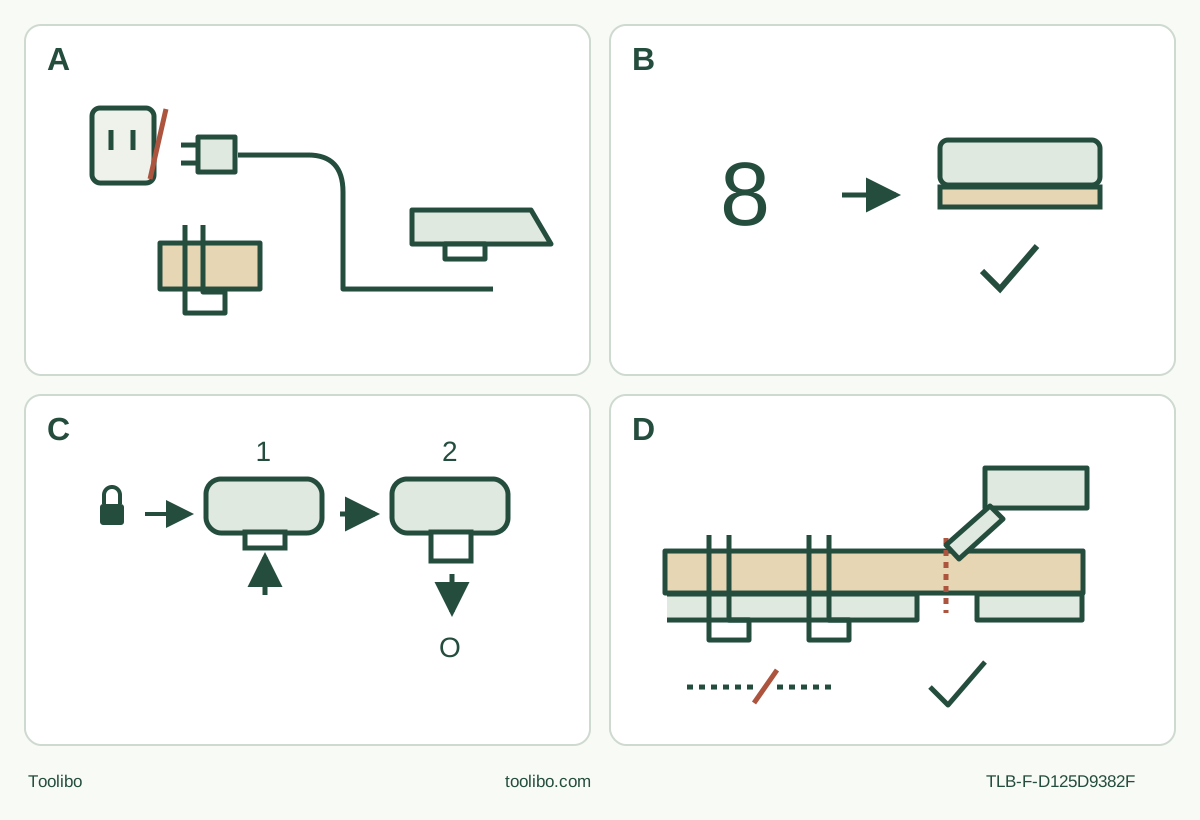
A · Unplug and route
Qualify actual supply and extension. Keep the disconnected cord away from the whole clamp and blade envelope during setup.
B · Eight plus flush
Remove the old blade, clean the interface and engage all eight pins with the correct native accessory flush to the shaft. Verify without power.
C · Press, then release
Cancel any continuous lock by pressing the trigger again and releasing it. Confirm fully OFF before reconnecting; momentary operation only for this sample.
D · Controlled separation
Clamp retained wood, independently support waste and keep the underside clear. Full stop and unplug before two-face acceptance.
Original schematic. A requires the actual nameplate-qualified supply, not a generic outlet approval. B is a conceptual check, not a drawing of pin spacing, accessory holes or interchangeable mounting geometry. C describes lock-ON cancellation, not a lock-OFF device; complete the check while unplugged before connection. D shows no rated depth or operating hand position; use the actual Figure 13 grip and verify the full blade path.
A Type 1 corded owner project, not a current-kit guide
Complete one short, visible separation in loose, new, uncoated softwood, using the actual recommended native wood blade. The finished result must be fully separated on the intended line, with controlled support and no uncontrolled tearing or scorching. This is not an installed-trim, blind-flooring or structural repair project.
This guide is limited to a physical DWE315 Type 1 whose supplied instructions and controls match N252379, JULY13. The complete manual is available at the manufacturer’s exact DWE315K/1 service-document path. That is a historical document identity, not proof that a current product page links this revision or that today’s kit has the same specification or accessories. Match the actual type and nameplate; if they differ or are unreadable, obtain the correct instructions before proceeding. The K packaging name does not create another tool body.
Do not import a current amperage, cord length or oscillation rating. This manual requires the supply to agree with the actual nameplate; it does not establish every body’s ratings from the model name alone. Nor does this trigger-operated tool have another model’s three-speed selector, battery isolation or five-minute lock-ON shutdown.
Qualify the actual supply, cord and work area
Before handling an accessory, establish OFF, cancelling any lock-ON by pressing the trigger again and then releasing it. Wait for complete standstill, then unplug the tool. Check the accessible cord, plug, housing, controls, clamp and blade. Damaged insulation, an unreliable switch, missing parts or unexplained looseness stops the project. Do not open the housing, repair a cord or connect power to reproduce a fault.
Use a suitable outlet and supply matching the actual nameplate. Never modify the plug. Keep cord and any extension clear of the blade, sharp edges, heat, oil, moving parts and trip hazards. Dry, well-lit bench work is the scope; do not work in wet conditions or near flammable liquids or gases. The manual specifies GFCI protection if damp-location use is unavoidable, but this project does not turn that provision into permission for wet work.
If an extension is necessary, use the exact printed table for the nameplate current, voltage and total length. Every segment must meet the minimum wire size; a smaller AWG number means a heavier conductor. For example, only if the actual nameplate is 120 V and more than 0 through 6 A, the table requires 18, 16, 16 and 14 AWG for total lengths of 25, 50, 100 and 150 feet respectively. This conditional example does not assign 6 A to the tool or qualify another voltage. If the actual supply or extension cannot be established, hold the work and seek competent assistance rather than guessing or adapting plugs.
Arrange ventilation and suitable dust collection under the actual equipment instructions. Use it correctly where provided; an attached hose alone is not proof of collection, and this manual does not identify a plunge-extraction assembly to invent. Wear certified ANSI Z87.1 eye protection (CAN/CSA Z94.3), ANSI S12.6 (S3.19) hearing protection and appropriate NIOSH/OSHA/MSHA respiratory protection for the dust. Direct particles away from the face and body. A small sample does not waive these precautions.
Choose the blade and check the whole cut
The manual’s compatible-accessory list includes Fastcut Wood, Hardwood and Wood Detail blade types, among others. Select the actual positively identified DEWALT-recommended native wood blade appropriate to this clean softwood and its required reach. A generic category in the manual does not identify an unknown blade in a second-hand kit. Do not invent a part number, use a metal blade by appearance or assume every advertised universal fitting is approved.
Inspect the blade for cracks, bending, damage and dull or excessively worn teeth. Keep the cutting tool sharp and clean. Check the actual mounted reach, orientation and complete oscillating envelope against the stock, clamps and support. There is no project depth rating inferred from the blade’s apparent length.
Check all faces and the whole route for nails, screws and other foreign material. Mark a short straight line from an accessible edge. Clamp the retained portion to a stable platform; independently support waste so it can separate without closing the kerf or falling onto the blade. Keep supports outside the complete blade path and make the underside visible and clear. Do not hold stock against your body or catch waste underneath. If the setup cannot provide that control, choose another sample or method.
Unplugged: remove the old accessory and seat all eight pins
Allow the old accessory and workpiece to cool. Handle sharp accessories carefully with protective gloves and keep fingers away from the cutting edges. Keep the tool unplugged throughout removal, fitting, orientation changes and retention checks.
Squeeze the accessory clamp lever and slide out any old accessory. Clean residual debris from the shaft and accessory holder. Slide the selected native blade between them, correctly facing, so it engages all eight locating pins and sits flush with the shaft. Release the lever. The manual illustrates alternative blade orientations, but use only one that retains the checked grip and clearance; no extra angular increment is invented.
Check even seating and secure retention while isolated. Do not add a washer to this native route, guess a torque or run the tool to test the clamp. If the correct clean blade will not seat and remain secure, stop for qualified service. This sample excludes the optional third-party adapter; its separate washer/accessory/nut instructions and retention warnings are not blanket permission to mix interfaces.
The optional guide block is also unnecessary for this simple edge cut. If considered for a different qualified task, the source distinguishes tabs into the side mount plus the supplied screw and key, a front-slot depth arm, and side-slot tracking of a marked line. The adjustment knob locks clockwise and releases counterclockwise. That does not establish an edge-fence contact, hidden-side clearance or a universal depth setting. Unplug for any such installation, adjustment or removal, and remove the key before later power connection.
Establish momentary control before connecting power
With the cord still unplugged, confirm that the variable-speed trigger is fully released and no continuous lock remains engaged. If necessary, press and release the trigger to cancel the lock, as the source describes. A switch that cannot be confirmed OFF is a service hold, not a reason to plug in and experiment.
Ordinary operation is proportional: pressing the trigger farther increases speed; releasing it stops the tool. But pushing the lock-ON button either left or right while the trigger is depressed latches the trigger. Once latched, taking your finger away does not stop it. Press the trigger again to release the latch, then release the trigger to stop. This project uses momentary control only. Do not describe that button as a lock-OFF device or rely on an automatic time limit.
The LED activates when the trigger is depressed. No delayed switch-off time is established here, and neither light nor darkness proves blade standstill or physical isolation. Avoid looking into the light.
If uncertain about speed, the manual says to test at low speed and gradually increase to a suitable level. Use a similarly supported spare piece, with the same material and blade. There is no universal wood trigger position or numeric dial recipe. Keep a secure grip and the blade clear when starting; establish the selected motion before contacting the wood.
Cut, stop and inspect with the plug removed
The exact operating Figure 13 shows one hand around the main body and trigger. Hold the insulated gripping surface securely, keeping the free hand away from the blade, cut and underside. Do not use that hand to compensate for insufficient clamping or transplant another model’s front-hand position. Keep vents unobstructed and the cord behind and clear of the whole cutting route.
After all assembly, support, dust and supply prerequisites are satisfied, confirm OFF once more and connect power. With the blade clear, use the momentary trigger, reach the selected operating speed and gently contact the marked edge. Advance with controlled light pressure. Do not force the blade, twist in the kerf or pry away an uncut bridge; excess force reduces efficiency and overloads the motor.
If the stock shifts, the blade binds, the cord approaches the cut, or there is unusual heat, noise or behavior, release the trigger and wait for complete standstill. If continuous lock was accidentally engaged, press and release the trigger to cancel it. Unplug before inspection. Do not run another attempt to reproduce an unexplained fault.
After complete separation, release the trigger, wait for full stop, withdraw along the clear path and set the tool down securely outside trip or fall hazards. Unplug before touching the work or changing setup, and let hot surfaces cool. Accept only the intended line and size, complete separation, stable support and absence of uncontrolled tear-out, scorching or stock movement. No dimensional tolerance is claimed. Correct a documented setup problem while isolated; unexplained tool defects require service. Success on this sample does not qualify hidden or installed work.
Separate care and service from an operating experiment
Keep the tool unplugged for cleaning and inspection. The manual calls for clean, dry air through the vents at least weekly, with ANSI Z87.1 eye protection. Non-metal exterior parts may be wiped with a cloth dampened only with mild soap and water; prevent liquid entering, never immerse and do not use solvents or harsh chemicals.
The source contains maximum-speed no-load cooling advice after ordinary prolonged low-speed heating. It is not a fault-recovery recipe for a damaged or unexplained stopped tool, and this guide does not ask the reader to energize such a system. Repeated circuit fuse or breaker trips require immediate discontinued use and authorized service, not repeated resetting or household electrical repair. Cord and switch replacement, internal adjustment and brush inspection belong to qualified service.
Sanding is a separate setup: the document’s brief powered step for seating an installed sanding sheet on a flat surface is an explicit adhesion procedure, not a powered clamp test. It does not belong in this blade-changing sequence or prove a complete sanding/dust system.
Source basis: DWE315 N252379 JULY13, complete English 1–10, actual clamp and guide/control figures, and back-cover revision. This is a document-based Type 1 owner workflow, not hands-on testing, a current-product backlink claim or a current-kit guarantee.
Models referenced