
Type, clamp, retained speed and two guide arrangements
Four panels show PCE605 Type 2 and form 90605797 with disconnected power, a squeezed and released clamp, forward ON and backward OFF with dial 1–6, and distinct front depth and side tracking guides.
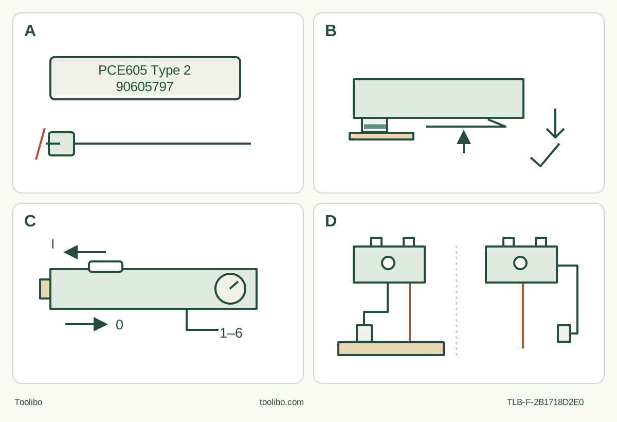
A · Match and unplug
Confirm the actual Type 2 and January 2014 instructions. Disconnect power before any accessory or guide adjustment.
B · Complete the lever clamp
Squeeze, clean, seat the approved accessory on all pins flush with the shaft and release. No locating-pin count is asserted.
C · Check OFF and the dial
With the head at left, forward is ON and backward OFF. Dial 1–6 remains set for the next start; it is not an isolation control.
D · Separate the guide jobs
The front slot sets depth; the side slots help track a line. The matching block needs its tabs and supplied screw, and neither guide detects hidden services.
Recovered original diagram freshly checked against actual manual pages 6–9. The tool head is left in C; D shows depth in side view and line tracking in plan view, not interchangeable guide positions.
Identify Type 2 before choosing an accessory
A PCE605 label alone is not enough to select an attachment. This guide is for an existing PCE605 Type 2 matching the manufacturer’s PCE605K/2 document path and January 2014 instruction form 90605797. The shared manual also names PCE606; that does not create a second model in this guide or establish that another revision shares the same accessory policy. Match the physical type, controls and supplied instructions first. This is not a current kit or latest-document claim.
The decisive rule appears in the assembly section: this version accepts only DEWALT Universal Fitment accessories and is not compatible with other PORTER-CABLE accessories. The later recommended-accessory warning does not cancel that explicit interface restriction. Do not transfer an older Type 1 rule, a familiar brand name or a Starlock assumption to this body. The same gate applies to a sanding platen, not just a cutting blade.
The owner outcome here is a secure, identified approved wood blade and a short cut in known untreated softwood removed from any structure. Both faces must be visible and the material securely supported. A matching optional guide can be checked on that sample, but hidden wall openings, live services, unknown paint and metal sanding are not part of the exercise.
Establish power and OFF before mounting
Inspect the actual nameplate, original plug, cord, housing and switch. The manual identifies a 3.0 A corded tool; the supply must match the actual nameplate. Its extension-cord table includes separate 120 V and 240 V rows, which is not permission to connect this particular tool to either voltage. Never modify a plug or use an incorrect supply to make the tool run.
Avoid an unnecessary extension. If one is needed, select its conductor size from the manual using actual voltage, nameplate current and total length, and use a cord suited to the environment. For a nameplate-matched 120 V, 3.0 A setup, the 0–6 A row gives 18 AWG for up to 25 ft, 16 AWG for 26–50 ft and 51–100 ft, and 14 AWG for 101–150 ft. Smaller AWG numbers indicate heavier conductors. Outdoor work requires an outdoor-suitable cord; unavoidable damp-location operation requires GFCI protection, not wet use of the tool.
Keep the slide switch fully backward at OFF and the plug disconnected throughout setup. Route the intact cord behind the work, away from the accessory, sharp edges, heat and the waste piece. Do not carry the tool or unplug it by pulling the cord. A damaged cord or unreliable switch requires authorized service, not a test cut.
Fit the approved blade without borrowing another clamp sequence
Identify an actual DEWALT Universal Fitment wood-cutting accessory recommended for this tool and suitable for the material and cut. Confirm its reach and instructions. A blade’s opening looking plausible is not enough. If the identity, compatibility or condition cannot be established, leave the cut pending. Check for cracks, bending, dull teeth and contamination; a damaged blade can bind or break.
With the plug out, allow any previously used blade and workpiece to cool and wear protective gloves. Hold the tool and squeeze its accessory-clamping lever. Clean residual debris from the shaft and accessory holder. Slide the blade between them so it engages all locating pins and sits flush with the shaft, then release the lever. Check secure seating while still unplugged.
Some blades and scrapers can be angled, but every permitted orientation must retain full pin engagement and flush contact. Do not force a partial fit or add an unapproved adapter or washer. This blade clamp does not require a threaded accessory bolt; the screw described below belongs to the separate guide block. To remove or reposition an accessory, stop, unplug, cool and squeeze the same lever again, keeping clear of its sharp edge.
Install a guide only when the exact parts are present
The manual marks the depth/cut guide as included with PCE605K only. That is a statement about the documented package, not a promise about a used tool or a current retail bundle. If the owner’s matching block, guide, screw and wrench are absent, the basic supported sample can proceed without a guide; do not substitute improvised hardware.
For a complete matching assembly, stay unplugged. Insert the block’s tabs into the slots in the main body, secure it with the supplied screw and tighten using the supplied hex wrench. Remove the wrench before connecting power. Check that the block is secure and does not obstruct the accessory.
The depth-guide arrangement uses the front slot. Slide the guide in or out to set the desired depth, then turn its adjustment knob clockwise to lock. Counter-clockwise releases it. Verify the actual resulting cut depth on scrap; the guide does not detect a hidden cable, pipe or rear surface.
The cut-guide arrangement uses the side slots on the left or right of the block. Set its length and lock the knob clockwise to help follow a marked line. It is not the same geometry as the front depth stop. Our diagram shows the depth arrangement from the side and the tracking arrangement in plan view. Neither arrangement replaces firm workholding, visibility below the blade or controlled entry.
Support the entire short cut
Mark a short line on the removed sample. Inspect both faces and the full blade path for fasteners or other foreign objects. Clamp the retained portion to a stable platform and support the waste so it cannot fall against a hand or close the cut. Leave clearance below and beyond the blade, and keep clamps out of the moving accessory’s area. Do not support the wood by hand or reach underneath it while cutting.
Use certified eye protection, suitable hearing protection and appropriate approved respiratory protection for the dust. Work with ventilation and suitable dust controls, keep bystanders out and clean exposed skin after dusty work. This exact manual does not establish a wood-cutting extraction hood or hose installation, so do not invent one. Ordinary glasses and the tool’s small size do not remove dust or eye hazards.
Hold both insulated grip areas firmly, keep a balanced stance and leave the vents clear. Keep the accessory working away from your body. Limit continuous vibration exposure with cushioned gloves, regular rest periods and sensible daily operating time. Unknown coatings and potentially hazardous materials remain outside this wood exercise.
Remember that the old dial setting survives OFF
The separate slide switch goes forward to ON and backward to OFF. The speed dial stays where it was set, so the next start uses that setting. Check both controls before plugging in; turning the dial low does not switch the tool off.
Positions 1–6 are approximate references, not calibrated guarantees. The manual gives approximately 10,000, 12,000, 14,000, 16,000, 18,000 and 22,000 opm respectively. Select a speed suitable for the approved blade and task. If uncertain, test at a low setting on scrap and increase gradually to a controlled working speed rather than assuming maximum is always correct.
After the mount, support, cord route and dial are checked, confirm full OFF and connect the qualified supply. Hold the blade clear of the sample, slide forward to ON and allow it to reach running speed before applying pressure. Feed slowly into the mark and advance along the line, letting the blade cut rather than forcing an excessive depth or jamming it.
Stop, diagnose and re-enter deliberately
If the sample shifts, the blade binds, the attachment moves or the sound becomes abnormal, slide backward to OFF. Wait for complete standstill and unplug before examining anything. Do not clear debris around moving teeth or use the guide as a lever to force the blade through. Correct the cause while isolated; unresolved damage requires service.
Do not restart with the blade in the work. Once the problem is resolved and the assembly is checked, start clear, reach full running speed and carefully re-enter. This rule also applies after an ordinary interruption. A retained dial setting is not protection against an unexpected start when the cord is connected.
For ordinary overheating associated with prolonged low-speed work, the manual describes maximum-speed no-load running for 2–3 minutes to cool the motor. That procedure is not a response to smoke, a damaged cord, repeated breaker trips, a loose blade or an unknown fault. Stop and isolate first to establish the cause. Only an otherwise sound, safely controlled tool may use the documented cooling procedure; do not force a restart or bypass a protective device.
At completion, switch OFF and wait for full stop before setting the tool down. Unplug, let the blade and sample cool, then inspect the cut, attachment and guide. Accept the result only if the retained material meets the intended need and no unexplained movement or damage remains. Refine support, accessory choice or technique on another sample rather than increasing force.
A later sanding task needs a separate qualified setup
A sanding platen must satisfy the same exact Type 2 accessory restriction. Install it with the unplugged lever-clamp sequence, then align a correctly sized sheet with the platen and press it on. Oversized paper can snag or injure. The manual’s brief powered adhesion step belongs only after assembly and safe connection, with the base against a flat surface—not while fitting or holding the paper.
Clamp the work, keep fingers off the platen and sand with light, long strokes. Check frequently, replace worn paper before it damages the pad and unplug before rotating or changing it. Do not wet sand or sand magnesium. For metal sanding the manual explicitly prohibits a vacuum because of sparks; this is not a universal instruction to connect extraction to every job. Metal and paint-removal workflows are not authorized by completion of the wood sample.
Finish with isolated care and a clear service boundary
Unplug before maintenance or storage. Clean with mild soap and a damp cloth, not harsh chemicals; do not immerse the tool or let liquid enter. Keep the cord, grips and ventilation areas in good condition. Do not open the motor or alter the clamp to accept another accessory system.
Repeated blown fuses or tripped breakers mean discontinue use and obtain authorized service; repeatedly resetting the supply is not troubleshooting. Damaged cords and switches also belong with qualified service. Retain the model, type, serial number and matching instructions for that handoff. Protect the cooled blade and store the disconnected tool securely. The dependable result is a complete Type 2 routine, not simply a blade that happened to fit.
Models referenced