
Voltage and lock states are different gates
A separates 12 V initial and 10.8 V nominal values with a not-equal cue and excludes a 20 V substitution. B shows the released trigger and lock-OFF cue. C shows a depressed trigger and continuous-operation cue. D shows five minutes is not the same as removing the battery.
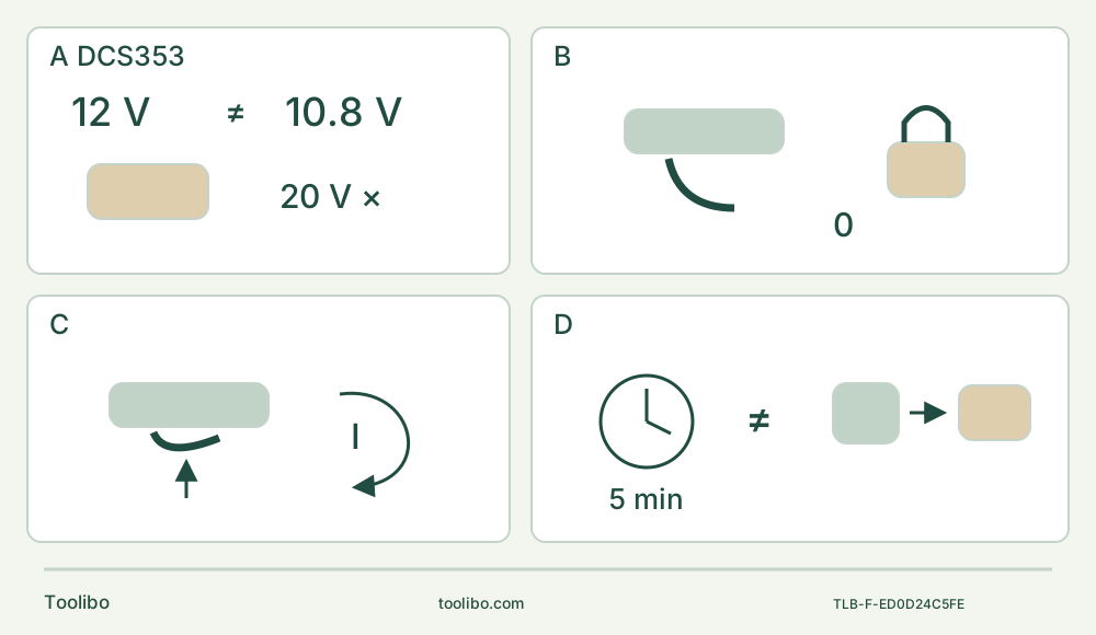
A · Match the actual platform
12 V MAX initial and 10.8 V nominal describe the selected system; use only the exact listed commissioned power items, not a 20 V substitute.
B · OFF before insertion
With the trigger released, the left-button click locks OFF. Still remove the battery before setup, accessory handling or acceptance.
C · Do not confuse continuous lock
The same button with the trigger depressed locks ON. Press and release the trigger to cancel and stop; this project does not use continuous lock.
D · Five minutes is not isolation
Automatic shutdown after five minutes applies to engaged lock-ON. Do not wait for it as a safety measure or treat a stopped tool as disconnected.
Original control schematic, not a wiring conversion, pin-count or charger diagram. A describes two voltage definitions for the same specified platform, not two interchangeable packs. B requires the released-trigger left-button click; C is the separate depressed-trigger lock-ON state, cancelled by pressing and releasing the trigger. D refers only to the documented lock-ON shutdown. This sample uses momentary operation and battery removal for isolation.
Finish one known-wood cut with the matched Canadian Type 1 system
This guide takes an existing DCS353 owner from a checked power system and native blade to one short, visible cut in loose, new, uncoated softwood, followed by battery-out acceptance. It is not an installed-flooring, hidden-service or structural repair project. The actual blade must reach the entire intended cut while the holder, work support and hands remain clear.
Match the Canadian DCS353 body and Type 1 instructions NA009481, September 2021, currently linked by the Canadian DCS353B product. B and G1 packaging names do not create different tool mechanisms. The product’s 12 V MAX is initial battery voltage without a workload; nominal voltage is 10.8 V. Do not substitute a 20 V platform, another regional DCS353 manual or DCS356 three-speed instructions.
The distinguishing workflow is a squeeze-lever, all-pin native attachment, a proportional trigger and a button that can lock either OFF or ON depending on the trigger state. The five-minute lock-ON shutdown is not an isolation method. This short project deliberately uses momentary trigger operation, not continuous lock-ON.
Qualify power and condition before fitting a blade
Use only an already commissioned original power system whose actual pack and charger are listed on this manual’s back cover and whose complete supplied instructions are available and satisfied. The listed packs are DCB120, DCB122, DCB124, DCB124G, DCB126, DCB126G, DCB127 and DCB127G. Listed chargers are DCB103, DCB104, DCB107, DCB112, DCB113 and DCB115. This guide does not commission a new pairing or teach charging.
Generic paragraphs about DCB118 and DCB1112 fan-cooled chargers do not add them to that list. Neither do battery names in the warranty section. Check actual identifiers, not just colour or a pack that appears to slide into the handle. Never modify or force a pack to fit. A fuel gauge indicates approximate remaining charge, not tool functionality, battery capacity or freedom from damage.
Do not use a pack or charger that has been dropped, received a sharp blow, been crushed or otherwise damaged. A cracked, leaking, wet, modified or overheated system is not a candidate for a sample cut. Follow the actual safe-disposition instructions and qualified service guidance, without opening a pack or improvising repair. Do not store or use the tool and pack where temperature may reach or exceed 40°C. Do not store a pack in the tool with the trigger locked ON.
With the battery removed, inspect the body, accessible vents, switch/button, clamp, original blade and any dust equipment. A switch that will not control the tool, unexplained looseness or damaged attachment parts requires service before use. Do not insert a battery to reproduce a suspected fault.
Select the actual native wood blade and dust system
The Canadian product lists a wood-cutting blade, and the manual’s compatible-accessory list includes wood-cutting types. Use the actual positively identified DEWALT-recommended native wood blade appropriate to this clean softwood task. A generic product listing does not identify every blade left in a used kit. If its identity, material approval, condition or reach is uncertain, obtain the correct evidence or stop; do not assign it an invented part number.
Reject dull, bent, cracked or otherwise damaged blades. Check the full oscillating envelope, installed reach and mounting orientation against the proposed stock. A long-looking blade does not establish a rated cut depth. This project uses no third-party adapter. The optional washer/accessory/adapter-nut procedure does not make every brand or shape safe; the manual still limits use to recommended accessories and warns against an application in which the adapter cannot retain the accessory.
Resolve dust controls before the cut, not after it. The safety instructions require appropriate extraction and respiratory protection. The actual suitable extractor, hose, connection and its operating instructions must be available and qualified for the material. A small sample is not an exemption, and an attached hose is not evidence of effective collection. If the system is incomplete, hold the cutting stage.
This model has a documented optional plunge-cutting extraction route, not only a sanding route. With tool battery removed and extractor isolated, first allow any fitted accessory to cool, wear protective gloves, squeeze the native clamp lever and slide the old accessory out without touching its sharp edges. Then attach the exact dust adapter with its tabs in the tool’s side slots and intake downward. Secure its supplied screw and washer with the supplied hex key, then remove the key. The manual permits its AirLock DWV9000-XJ connection or standard 35 mm fitment under the actual equipment instructions. Push the correct extraction arm into the adapter’s lower aperture before fitting the plunge blade, then adjust the arm as documented. Keep the arm and hose clear of the full blade path and the required grip. Missing actual components, poor retention or an unresolved downstream extractor holds this route; no substitute parts or capture percentage is inferred.
Battery out: complete the native clamp
Keep the trigger released, the tool OFF and its battery removed. Allow the old accessory and work to cool. Wear protective gloves when handling or changing sharp cutting accessories and keep fingers off the edges.
Squeeze the tool-free accessory clamp lever. Clean residual debris from the tool shaft and clamp holder. Slide the selected accessory between shaft and holder so it engages all locating pins and lies flush with the shaft, then release the lever. Use only a documented blade orientation that suits the checked path. The schematic does not establish a pin count or an interchangeable mount standard.
Check the fully seated, retained accessory while isolated. Do not add a washer to this native route, borrow an adapter nut, guess a tightening torque or run the tool to see whether the blade stays attached. If the correct clean accessory will not sit flush and remain secure, stop for qualified service.
Optional cut-guide parts are not needed for this sample. The source distinguishes a side-slot arm that tracks a marked cut line from a front-slot depth arm; it does not turn the side arm into a proven edge fence or guarantee clearance behind hidden work.
Know what the trigger and lock button will do
Before inserting the battery, confirm the trigger is released and any continuous lock has been cancelled. The button can lock OFF when pushed fully left until it clicks with the trigger released. That is not physical isolation: remove the battery for adjustments, accessory handling and acceptance.
When the trigger is depressed, pushing the same button left locks the trigger ON. Pressing the trigger again releases that lock; releasing the trigger then stops the tool. Never assume releasing your finger will stop a tool left in lock-ON. The manual specifies automatic shutdown after five minutes with lock-ON engaged. It is not a promise to stop a dangerous cut soon enough, a five-minute safe-use allowance or proof that a stopped tool is disconnected. This project avoids lock-ON entirely. Before starting, the owner must already understand and establish a functioning released, unlatched momentary control, with any lock-OFF correctly disengaged under the actual owner instructions. If that state cannot be established, hold the project; do not experiment with the switch under power.
The LED lights when the trigger is pressed and remains lit briefly after release; no precise delay is specified. Do not stare into the light. Its illumination or darkness is not evidence of blade standstill or battery isolation.
The trigger controls speed continuously: more pressure means faster motion. If uncertain about the proper speed, the manual says to test at low speed and increase gradually until suitable. Do not invent a numbered wood setting or transfer another model’s three-speed selector. For a restart after interruption, the blade must be clear of the work; let the tool reach operating speed before carefully re-entering, rather than restarting inside the cut.
Prepare and complete the sample
Inspect every face of the loose softwood and the entire cut route for nails, screws, other foreign material and services. Mark a short straight separation from an accessible edge. Clamp the retained part to a stable platform, with independent waste support that permits separation without closing the kerf or dropping waste onto the blade. Keep every support and clamp outside the full motion envelope. Never hold the stock by hand or catch the waste underneath.
Operate and check the actual extractor under its own instructions before cutting; if its required operation cannot be established, hold the cut. Provide ventilation, good lighting, secure footing and clear access. Wear certified eye protection to ANSI Z87.1/CAN/CSA Z94.3, hearing protection to ANSI S12.6 (S3.19), and suitable NIOSH/OSHA/MSHA respiratory protection. Follow the manual’s vibration precautions, including cushioning gloves, frequent rests and limited daily use; no invented safe exposure duration is offered. Keep clothing, hair and gloves away from moving parts.
The exact proper-hand-position figure shows one hand on the main handle. Grip that insulated handle securely in anticipation of a sudden reaction. Do not transplant a different tool’s front-hand position, cover the vents or use the free hand to steady the work. Keep it away from the cut and underside.
Once the setup is complete, switch OFF and trigger released, align the qualified pack with the handle rails and slide it fully home. Verify it cannot disengage. With the blade clear, start using the qualified momentary control, let the blade reach the selected operating speed, and only then contact the wood and guide it on the marked line with controlled pressure. Do not jam the blade, force excessive depth, twist it in the kerf or pry away a remaining wood bridge. Excessive force reduces efficiency and overloads the motor.
Release the trigger for binding, work movement, abnormal heat or behavior, or any obstruction to the grip, hose or cut path. Wait for complete stop and remove the battery before investigation. If a continuous lock was accidentally engaged, press and release the trigger to cancel it and stop. Do not reproduce faults under power.
After full separation, release the trigger, wait for standstill, withdraw along the clear path and place the tool on its side on a stable surface where it will not create a trip or fall hazard. Press the battery release and pull the pack out before inspecting the work or changing setup. Accept only the intended line and size, complete separation and controlled support, without uncontrolled tearing or scorching. There is no claimed dimensional tolerance. Correct a documented setup problem while isolated, or seek service for unexplained tool behavior.
Keep cutoff, cooling and care separate
A protective shutdown is not permission to keep pressing the trigger. The troubleshooting table distinguishes a depleted pack from a pack at its thermal limit; follow the actual power-system instructions and allow cooling where required. The separate advice to run an ordinarily hot motor at maximum no-load speed for two to three minutes after prolonged low-speed work must not be used to override a protection-stopped, damaged or unexplained system. This guide offers no fault-cooling experiment.
Remove the battery for care. The manual calls for clean, dry air through tool vents at least weekly with ANSI Z87.1 eye protection. Use only a cloth dampened with mild soap and water on non-metal tool surfaces; prevent liquid entering and never immerse. Pack and charger exteriors instead use a cloth or soft non-metal brush without water or cleaning solution; unplug the charger first. Internal repairs belong to qualified DEWALT service.
Sanding is a separate setup and result. The manual contains a specific brief powered adhesion-seating step for an installed sanding sheet, but that exception is not a powered clamp test and does not belong in this blade procedure. Do not infer a completed sanding system from a successful wood cut.
Source basis: DCS353 NA009481 09/21, full English 6–15, illustrated pages 1–5 and back-cover power table; current Canadian DCS353B product and its exact Type 1 manual link. This is a document-based owner workflow, not physical testing or a current-kit guarantee.
Models referenced