
Native clamp, three control states and a complete sample
A shows a pack separated from the body. B shows a neutral native clamp squeeze and flush-blade cue, not a counted pin layout. C separates a released trigger with side lock, centre enable and a depressed trigger with side lock. D shows the main-handle grip, clamped retained stock, independent waste support and blade clearance.
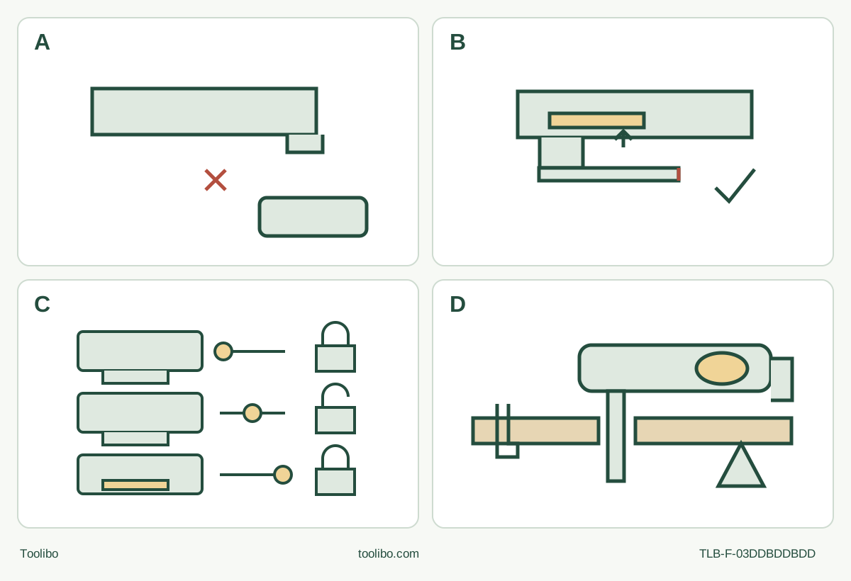
A · Fully isolate
Cancel maintained ON if engaged, release to OFF, wait full standstill and press the battery release to pull the pack completely out.
B · Native clamp only
Squeeze the lever, remove the old cooled blade, clean and seat the approved replacement on all eight pins flush with the shaft. Release and check while isolated.
C · Keep the trigger states distinct
Released trigger plus side button locks OFF; centre permits momentary control; pressed trigger plus side button locks ON. Press again then release cancels ON.
D · Complete and inspect
Use the actual main handle and clear other hand, maintain clamp/free waste support, stop fully before withdrawal and safe side setdown, then remove the battery and inspect.
Original conceptual schematic. B still requires all eight actual pins engaged and flush shaft seating; the neutral drawing does not specify their layout. C is not a powered test: centre enables momentary operation, and a latched ON state requires trigger press-again then release to stop. D uses the actual main handle, not another model’s two-grip template; stop fully, lay on the side safely and remove the battery before inspection.
A dated Canadian Type 1 owner, not every DCS355
Use this guide only if the actual Canadian DCS355 Type 1 and its supplied N434640, JUN15 instructions match the body, controls and nameplate in hand. The official service listing distinguishes Type 1 from Type 2, but its current manual-download link has not been verified as selecting this June 2015 document. The official dated QUCA Type 1 document is the operating authority here. If your revision or physical type differs, obtain the correct instructions instead of merging procedures.
The project is a short, complete separating cut in known dry, untreated, uncoated loose wood. Both faces, the route and the blade exit remain visible; the retained piece is clamped and the waste independently supported. It excludes installed trim, hidden wiring or plumbing, structural modifications, guide-assisted depth cuts and adapter-mounted accessories.
Before beginning, positively identify an actual original DeWalt-recommended native wood-cutting blade, its intended material, sound condition and usable reach. The matched manual lists wood, hardwood, fast-cut wood and wood-detail accessory categories but does not supply a specific part number for this project. Therefore, the blade’s own documentation and actual identity are a prerequisite, not a gap to fill with an invented SKU or a current kit photograph. If that evidence is missing, hold the project.
Qualify the existing power system and condition
This bounded setup uses the owner’s already commissioned, genuine DCB203 battery and DCB112 charger, with their complete actual instructions and nameplates. The dated final compatibility table supports that pair; a current Canadian combo also names these components, but it does not establish this tool’s physical type, supplied manual or original package contents. This is not a first-charge tutorial, a new-pair selection or permission to substitute another pack or charger.
The 20 V Max designation means 20 V maximum initial voltage without load and 18 V nominal, not a different 20 V nominal platform. A battery that slides into the handle or lights a gauge is not proof of compatibility or condition. The optional fuel gauge indicates approximate charge only, not tool functionality, capacity or safety.
Do not use a battery pack or charger that has received a sharp blow, been dropped, run over or otherwise damaged. Cracked cases, damaged contacts, an unreliable charger cord or unexplained behaviour require qualified service and safe disposition under the actual equipment instructions. Do not open, modify, salvage, bridge terminals or improvise shipping instructions for a damaged pack. Keep loose conductive objects away from exposed terminals.
The dated manual prohibits using or storing the tool and pack where temperatures may reach or exceed 40 °C. That is not a charging-temperature recipe, and charging conditions must not be inferred from it. If the commissioned system’s condition or instructions are unresolved, stop here rather than borrowing another owner’s settings.
Set out a visible, controlled bench task
First establish OFF. If lock-ON is engaged, pressing the trigger again releases it and releasing the trigger then stops the tool. Wait for full standstill. Press the battery release button and pull the pack fully out of the handle before inspection, adjustments or accessory changes. A trigger lock is not electrical isolation.
Inspect the isolated housing, main handle, trigger, lock button, clamp lever, shaft and holder. Loose or damaged parts, binding controls, cracks or an uncertain mechanism require qualified correction. Do not power the tool to reproduce a fault. A failed switch must not be worked around by treating battery insertion and removal as the normal switch.
Use a dry, stable, well-lit work area away from flammable liquids, gases and explosive dust. Keep bystanders clear. Inspect the wood and entire cut route for nails, screws, staples, embedded debris and unknown finishes. Clamp the retained section to a stable platform; independently support the waste so it can separate without pinching the blade. Verify that the complete oscillating envelope and below-face exit avoid the bench, clamps and supports. Hands and your body are not substitutes for workholding.
Use certified eye protection meeting ANSI Z87.1/CAN/CSA Z94.3 and hearing protection meeting ANSI S12.6 (S3.19). The manual also requires NIOSH/OSHA-approved respiratory protection appropriate to dust exposure; ordinary spectacles and ventilation alone do not replace it. Control dust away from your face and body, protect nearby people and follow the actual material information.
Qualify the actual task-suitable dust equipment and its own instructions before cutting. With the tool OFF, stopped and battery removed, and the extractor isolated under its instructions, complete the documented connections. Then operate and check the actual system as instructed before the cut. This manual does not establish a specific plunge-capture arm, sanding hood or installed airflow threshold for this project. Do not borrow another DeWalt’s geometry or declare an improvised connection adequate. Unresolved dust control is a hold, not an invitation to make a dusty test cut.
Fit the native blade completely
With the battery still fully removed, let any old blade and workpiece cool. Avoid sharp edges; suitable handling gloves do not permit touching a moving accessory. Squeeze the actual accessory clamp lever, slide the old native blade out and remove it before fitting the replacement. Do not stack accessories.
Clean residual loose debris from the shaft and accessory holder without modifying either. Slide the positively identified original blade between the shaft and holder. It must engage all eight holder pins and sit flush with the shaft. A blade resting on top of a pin or only partly engaged is not ready. Choose an orientation consistent with its own instructions and the clear sample route; angled mounting does not grant extra cutting reach or approve another accessory family.
Release the clamp lever, then check secure seating while isolated. There is no native bolt-tightening, torque, hex-key or adapter step in this selected route. If full engagement cannot be established, stop for identification or service rather than energising the clamp to see whether it seats itself. Inspect the actual cutting edge and blade for dullness, cracks, deformation, breakage or other suspected damage; reject doubtful accessories.
Compare actual usable blade reach with the supported sample while power remains removed. There must be space for complete separation and a stopped exit without striking a support. Do not treat a chosen sample thickness as a manufacturer rating or force a blade beyond its documented purpose.
Understand the three button states before inserting power
The variable trigger is A; the lock-on/off button is D in the matched manual. With the trigger released, pushing D fully to either side until it snaps into position locks the trigger OFF. D in the centre permits normal trigger operation. With the trigger already depressed, pushing D to either side instead locks it ON. To cancel lock-ON, press the trigger again and then release it; the tool turns off on release.
Those are distinct states of the same button. Do not assume a side position always means safe OFF, and do not confuse releasing a latched trigger with stopping the tool. The sample uses momentary trigger control, not maintained lock-ON. If the owner cannot establish the actual released, functioning control and correct centre position, hold for the proper instructions or qualified correction without a powered switch experiment. No five-minute shutdown behaviour is claimed for this documented body.
Before inserting the pack, confirm the switch is fully OFF and the trigger released, with clamp, blade, support and dust arrangements qualified. Align the approved pack with the handle rails, slide it fully into place and confirm it is securely seated and cannot disengage. Keep fingers away from the trigger during insertion. Establish the centre-enabled momentary state deliberately before starting, with the blade clear of the stock.
Make the sample under momentary control
Use the main-handle grip shown in the exact Figure 16, with stable footing and control against unexpected movement. Keep the other hand, face and body clear of the blade and its whole path; do not reach underneath the wood or invent a second grip on the head or clamp lever. Keep clothing and hair away from vents and moving parts.
Press the trigger with the blade clear and establish controlled running before contacting the wood. Further trigger depression increases speed. If uncertain about the proper working speed, the manual directs starting the performance trial at low speed and gradually increasing to a comfortable controlled rate. This applies only to the already qualified sample and accessory; it is not permission to test an uncertain assembly. There is no numeric wood OPM setting supplied here.
Guide the blade along the visible marked route without excessive pressure, twisting or levering waste out. Keep retained clamping and free waste support effective through full separation. Excess force reduces efficiency and overloads the motor. If wood moves, the kerf traps the blade, visibility is lost or the tool behaves unexpectedly, stop rather than repositioning anything around a moving accessory.
The LED comes on whenever the trigger is depressed and remains on for 20 seconds after release. Do not stare into it. Illumination is not proof that the blade is running, stopped or isolated, and darkness is not a readiness check.
Stop, lay it on its side and accept or hold
For this project, release the momentary trigger—or cancel lock-ON by the documented press-again-and-release action if it was engaged—then wait for complete standstill before withdrawing along the clear path. This conservative stopped-before-withdrawal sequence is the chosen sample procedure, not a claimed verbatim OEM withdrawal rule.
Place the stopped tool on its side on a stable surface where it cannot trip anyone or fall. Do not stand it on the pack. Press the battery release and remove the pack fully before touching the accessory or inspecting the sample; allow hot parts to cool. Never store it with the trigger locked ON or tape the trigger down.
Inspect both faces and the whole edge. Accept only complete separation along the intended line and size, without uncontrolled tear-out, scorching, shifted clamping or trapped-waste marks. No numeric tolerance or finished-joinery guarantee is implied. A poor sample requires a documented correction to blade, approach, support or dust control; unresolved holder, control, power or identity problems require qualified service before another attempt.
Keep care isolated and follow the matched cleaning instructions without liquid ingress or harsh solvents. Internal repairs, brush work and adjustments belong to qualified service using identical parts; the pack and charger are not owner-serviceable. Do not use a high-speed cooling run or repeated no-start trials as a fault-diagnosis recipe here. Retain the actual type, serial/nameplate information, supplied revision and observed symptom without reproducing it. The dated warranty pages do not establish current coverage.
Source basis: official Canadian Type 1 service identity; DCS355 Instruction Manual N434640, JUN15, full English pages 1–16 and final compatibility/footer page 60, especially native clamp page 10 and controls page 13; current Canadian combo listing only for regional model/component identity. The current service manual-selection link is not claimed verified.
Models referenced