
Documented assembly, distinct controls and visible cutting
A shows a document beside an unchanged blade-equipped body and a separated battery, with a question mark at the mounting boundary. B separates a slide switch from a 1–6 dial. C shows two grip highlights, clamped retained stock, independent waste support and a blade extending into clear space.
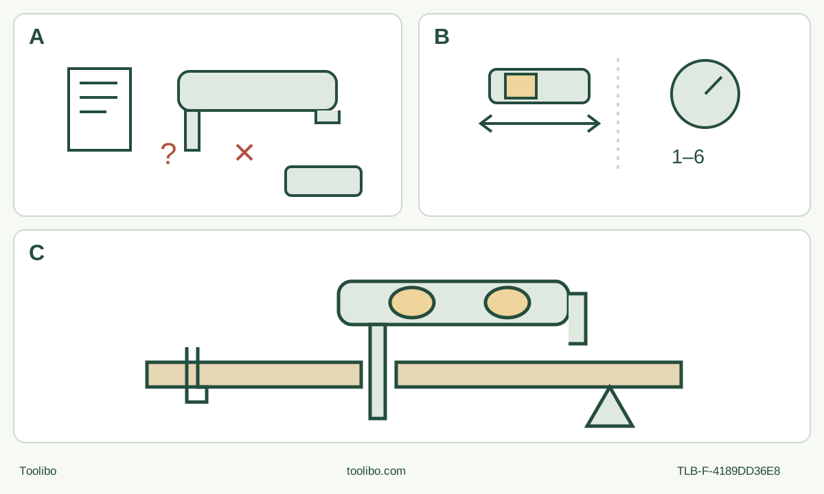
A · Evidence before operation
Actual Type 1/document match and manufacturer-qualified original installed wood-blade assembly are prerequisites. Remove the pack; do not operate the clamp or infer safety from appearance.
B · Separate switch and speed
Forward slide starts; backward slide stops. The separate 1–6 dial has approximate reference speeds, not an automatic material choice. Establish OFF before battery insertion.
C · Complete the supported sample
Keep both hands on the tool, the retained portion clamped and waste independently supported. Start clear, feed without force, stop fully, set down safely on the side and remove the pack before acceptance.
Original conceptual schematic. A is an evidence prerequisite, not a visual certification or clamp instruction; unresolved mounting stays held. B does not depict a variable trigger or prescribe a wood dial value. C requires both hands for cutting; supports remain outside the whole path, and full standstill plus battery removal precede acceptance.
Start with a documented assembly, not a loose blade
This project is for an existing US CMCE500 physical Type 1 whose supplied instructions match NA484461, September 2023. It is not a first assembly, a buying recommendation or a guide for every body advertised as CMCE500B. The current US product page links the same document through Type 1 and Type 3 service paths; identical downloads do not establish interchangeable physical types. The operating instructions describe a forward/back slide switch and a separate speed dial, despite the product page’s variable-speed-trigger wording.
There is an important unresolved installation problem in that document. Its numbered procedure says to release the accessory clamp lever before sliding in the accessory, while Figure B depicts squeezing and insertion. The translated procedures repeat the order. This guide does not correct that sequence by guesswork or teach removal, refitting or reorientation. Do not operate the clamp as part of this project.
Proceed only with positively documented manufacturer-qualified installation of an original CRAFTSMAN-recommended wood blade already on this exact tool. The owner must know its identity, intended wood use and correct installed assembly—not merely recognise a similar blade in a photo. With the battery removed, its matching pins must be fully engaged and the blade flush with the shaft, as the manual requires. Appearance alone does not prove identity, correct assembly or safe condition. If the documentary history, secure seating or actual blade suitability cannot be established, keep the tool out of use and obtain manufacturer clarification or qualified service. A loose, shifted, damaged or wrongly oriented blade is an exit, not an invitation to try the lever or run a seating test.
The outcome is one fully visible crosscut in loose, new, dry, uncoated softwood, followed by battery-out acceptance. No installed trim, hidden services, metal, paint, structural member, accessory adapter or sanding operation is included.
Qualify the existing power system and inspect without disturbing the mount
The manual’s final table lists compatible original battery packs and chargers, but page 2 also requires the original or separate battery-and-charger instructions. Use only an already commissioned listed system whose actual instructions, condition and operating limits are understood. This article does not commission a new pair or teach charging. The final table prohibits storing or using the tool and battery where temperature may reach or exceed 104 °F (40 °C); that use/storage limit is separate from the charging-temperature instructions, which still require the actual power-system documentation. The designation is 20 V maximum initial voltage and 18 V nominal, not 20 V nominal. Missing power instructions or an unidentified, modified or damaged power item means hold for qualified advice; never open or repair a battery or charger.
Before handling the tool, slide its switch fully backward to OFF, wait for complete standstill, press the battery release button and pull the pack completely out. Keep the removed pack protected under its own instructions. The light or a low dial position is not isolation. Let the blade and work cool before approaching them; use protective gloves for sharp-accessory handling without disturbing the clamp.
Inspect the housing, main handle, accessible original parts, switch and installed blade. Dry, clean gripping surfaces and a reliable OFF control are essential. Reject cracks, bent or dull teeth, suspected damage, unexplained movement or an unreliable switch; do not reproduce a fault under power. Do not add washers, tighten guessed fasteners or substitute another brand’s mounting rule. Any need to change the blade ends this project until the unresolved installation procedure has been properly clarified.
Make the workpiece and cutting route genuinely visible
Choose a small sample you can securely support and a cut that the already installed blade can complete without reorientation. “Small” is a project choice, not a manufacturer capacity or safe-size exemption. Check the actual wood identity and dryness, both faces and the full route for nails, screws, inclusions, coatings and concealed items. Inspect the blade’s actual usable reach and swept width against the marked line and full thickness. If you cannot see and keep the complete path clear, select another sample or stop; do not force a deeper cut.
Clamp the retained portion to a stable bench. Support the waste independently so it cannot fall uncontrollably, yet can separate without pinching the blade or closing the cut. Neither a clamp, bench edge nor support may enter the blade’s full path beneath the wood. Keep hands out of that path and never reach under the sample. Do not hold the work against your body or use the tool to stabilise it. Mark the intended line and identify which side is waste before connecting power.
Work in a dry, well-lit, ventilated area with stable footing, bystanders clear and no flammable or explosive atmosphere. Wear certified ANSI Z87.1/CAN/CSA Z94.3 eye protection, ANSI S12.6 hearing protection and appropriate NIOSH/OSHA respiratory protection. Use cushioned gloves, take frequent rest breaks and limit vibration exposure. These measures are not replaced by dust collection. Where a suitable collection system is used, first keep the tool OFF, stopped and battery-out and isolate the extractor under its instructions before connecting equipment. Then operate and check the actual qualified dust system as its instructions require before cutting. No native cutting hood or numerical airflow capability is established here.
Start clear and let the selected speed settle
The separate dial has positions 1–6, approximately 8,000, 10,000, 12,000, 14,000, 16,000 and 18,000 oscillations per minute. These are reference values; the manual says actual speed can vary. They are not a universal wood recipe. If the appropriate setting is uncertain, its procedure is a low-setting trial followed by gradual increase until a suitable result is found. Choose the setting while isolated for this sample, keeping any required blade limits and the actual task instructions controlling.
Recheck the workholding, clear blade path and unaltered qualified assembly. With the switch fully OFF, align the commissioned battery with the handle rails, slide it firmly into place and ensure it cannot disengage. Keep the blade clear of the wood, supports and body. The general hand-position illustration shows a main-handle grip, but the cutting section expressly requires both hands for all cutting operations. Hold the tool securely with both hands on appropriate insulated gripping surfaces, keeping fingers clear of the blade, moving parts and vents; do not invent an auxiliary handle.
Slide the switch forward to ON. For this project, let the selected operating speed settle with the blade clear before bringing it to the marked start. Feed slowly and guide along the line without excessive pressure or jamming. Let the teeth work rather than bending the blade or forcing depth. Watch the waste support and keep both hands on the tool, not on the offcut. A stalled blade, moving workpiece, unusual vibration or suspected mounting change requires stopping—not more force or a different dial position.
Stop, isolate and decide whether the sample passes
When separation is complete, slide backward to OFF. For this sample, the conservative chosen sequence is full standstill before withdrawing along the clear path; this is a project rule, not a quotation of an additional manufacturer instruction. Set the stopped tool on its side on a stable surface outside trip or fall hazards, then remove the battery before inspecting the result. If cutting is interrupted, do not restart in the workpiece: the manual requires the tool to reach full speed before carefully re-entering a cut. Re-entry is not allowed here until the isolated workholding, blade and unchanged documented assembly remain qualified.
Accept the sample only if the intended line and size were achieved, the cut broke through completely and there was no uncontrolled tear-out, scorching or shifted support. No numerical tolerance is promised. If only the documented workholding or line placement needs correction, correct it while isolated before another sample. If the blade is unsuitable, worn, loose or suspect, stop for the mounting clarification or qualified service already required; this article supplies no replacement shortcut.
Clean accessible external surfaces under the matched maintenance instructions without disturbing the blade assembly: do not immerse the tool or allow liquid inside, and avoid solvents or harsh chemicals on plastic. Leave battery and charger service to qualified providers. A thermal shutdown, abrupt stop or other fault is not permission to use a no-load cooling routine as a diagnostic test. Keep the evidence of the actual tool, blade and installed assembly with the service request rather than recreating the fault.
Evidence used
CRAFTSMAN CMCE500 instructions NA484461, September 2023: cover and page 2 for identity and separate power instructions; English pages 4–6 for preparation, condition and protection; pages 6–7 and Figure B for the unresolved installation order and required seating; page 7 and Figures F–I for battery, control, speed and cutting; pages 8–9 for care and service boundaries; final page 24 for the compatible power list and nominal-voltage note. The current official US CMCE500B product page establishes its document links and original Wood Blade category, not a blade SKU, current kit promise or a corrected mounting procedure.
Models referenced