
Isolation, full mechanical clamp and qualified sanding
A shows a separated battery and original bolt/key inventory beside a temporary magnetic positioning cue, without counted holder geometry. B shows a sanding plate and native hood/hose connection as separate system components. C shows a level-4 ceiling and a supported broad face with two grip-planning highlights.
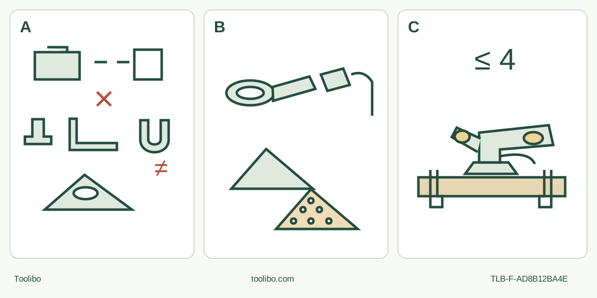
A · Isolate and complete the clamp
Remove the battery and old attachment. Magnet positioning still needs the original bolt, flush tightening, isolated security check and key removal.
B · Close the whole extraction route
Fit the matching hood before the plate, align the original sheet holes and qualify the actual adapter, hose and extractor before producing dust.
C · Sand, stop and accept
Use both hands, light consistent pressure and no more than level 4. Switch 0, wait full stop and remove the battery before surface acceptance.
Original conceptual schematic. A is an inventory and isolation cue, not an exploded assembly or torque instruction. B requires the exact Figure D hood, correct mounting order, aligned holes and a qualified actual extractor; a hose line alone is not capture approval. C indicates the sanding ceiling, not a universal optimum, exact grip contour or finish tolerance.
A complete face-sanding project, not a magnet test
This route is for the UK Bosch UniversalMulti 18V-32, order 0603105000, with an actual matching body and supplied instructions. The selected operating document is 1 609 92A 87V: cover 2024.02, footer 07.12.2023; its UK declaration identifies 3 603 A05 000. Later declaration downloads are not replacement operating procedures. This is one body, not a claim that every current package contains the same power or extraction equipment.
The finished outcome is an evenly sanded accessible face on known, dry, uncoated loose wood, followed by a battery-out inspection. It is not installed trim, unknown paint removal, a blade-cutting lesson or a surface-quality guarantee. The original AVZ 93 G, 93 mm sanding plate and an appropriate original Bosch wood sheet must be positively identified. A magnetic hold is only a positioning aid: the original bolt and hex key still complete the mechanical clamp.
Do not start without the complete dust system. The matched manual requires extraction for sanding, not merely for a large area. Before proceeding, identify the actual Figure D hood, connector and hose, and a material-suitable extractor whose own instructions establish the complete installed arrangement and safe operation. A small sample is no exemption. A product recommendation for a legacy-named hood, a hose that happens to push on, or the connection illustration on page 130 does not prove dust suitability. If those checks remain unresolved, the outcome is a documented equipment hold, not a trial with improvised capture.
Qualify the power system and work area
Use an already commissioned original PBA 18V…W-. battery system with its actually compatible AL 18… charger and their own instructions. The tool table explicitly excludes AL 1814 CV, AL 1820 CV and AL 1860 CV with these batteries. Do not infer compatibility with a Bosch Professional pack or another similarly named charger. This guide neither selects a new charging pair nor substitutes a charging recipe.
Keep the temperature contexts separate: the tool table recommends 0–35°C ambient during charging and permits −5–50°C during operation and storage, with reduced performance below 0°C. The separate battery-handling paragraph gives −20–50°C storage for the battery; that does not extend the whole tool’s storage permission. The actual pack and charger instructions still govern their use. Damaged, altered, wet or suspect equipment is not commissioned equipment.
Move the switch rearward to 0, wait for complete standstill, press the battery release button and pull the pack fully out without force. Isolate the actual extractor under its own instructions before assembly. Inspect the housing, switch, holder, original bolt/key, pad, sheet, auxiliary handle and accessible connections. Cracks, unreliable controls, loose or damaged parts, distorted mounting surfaces or unexplained condition require qualified correction, not a powered seating test. Wear protective gloves when changing accessories and allow hot attachments to cool. Keep the tool’s magnet away from implants such as pacemakers or insulin pumps, and from magnetically sensitive equipment and media.
Choose sound wood with a known history and no coatings, solvent contamination, metal or embedded debris. Clamp it to a stable support with the intended face accessible and the clamps outside the whole tool, pad and hose route. Do not hold the work in a free hand. Establish stable footing, good light, ventilation and a clear bystander area. Wear eye and hearing protection and suitable respiratory protection for the actual dust assessment; the manual recommends a P2 filter-class respirator. Extraction does not replace eye or hearing protection. Keep the wood and workplace dry: this is dry sanding only.
Assemble the exact hood before the pad
With the tool and extractor isolated, remove any cooled old accessory: use the original hex key to loosen and remove its clamping bolt, then remove the accessory. Remove a fitted segment-blade depth stop as well; it is not part of the sanding stack. Keep the actual original hardware together rather than adding washers or borrowing another model’s fastener.
Slide the matching dust hood fully over the accessory holder onto the tool collar. Turn it to a useful position, but not directly underneath the tool, and close the hood’s own clamping lever. The Figure D hood is for sanding; its illustration crosses out the saw and other non-sanding shapes. It is not a general blade-capture device.
Now fit the original plate onto the holder so its depressed centre faces down, its upper marking remains readable and the holder cams engage. The system provides twelve positions at 30° intervals; that describes accessory orientation, not a key-turn instruction. The magnet temporarily supports positioning. Install the original clamping bolt and tighten it with the original hex key until the bolt is flush with the accessory, then check secure seating while still isolated. Do not invent a torque, substitute a screw or leave the magnet as the clamp. Remove the hex key before any later power connection.
Clean the plate’s hook-and-loop surface by tapping it clear. The manual’s wood-sheet table includes 80, 100 and 120 grades for surface levelling; select an actually identified original sheet appropriate to the intended finish rather than assuming a supplied grit. Align its edge and punched holes with the plate and press it firmly into place. Use an intact sheet; do not reuse one that has worked metal. There is no powered adhesive-seating step in this procedure.
Insert the matching extraction adapter into the hose until it clicks, connect the adapter to the hood outlet, and connect the hose to the qualified extractor. Follow that extractor’s instructions for its collection system, checks and operation. For dry dust that is especially harmful to health or carcinogenic, use a special extractor as the matched manual requires; its dust warning includes oak and beech. Page 130 maps connection options; it is not a certification of every material, filter or installed capture performance. Do not transplant a different Bosch manual’s numerical suction requirements. Route the hose without pulling the tool, restricting either grip or crossing the stance.
Screw the sound original auxiliary handle into the left or right threaded mounting point as appropriate to the actual approach. Do not use a damaged or modified handle. Plan a firm two-handed hold with the switch reachable without releasing the handle and the ventilation slots unobstructed. If the chosen clamp or hood position prevents this, change the isolated arrangement before proceeding.
Sand the whole intended face
Confirm the switch remains at 0 and the key is removed. Only after the complete setup is qualified, insert the verified charged battery until it clicks. Operate and check the extractor under its own instructions before producing dust. Set an appropriate sanding speed no higher than level 4, also respecting any lower limit on the actual accessory or its packaging. The manual’s wood-sawing recommendation of 6 is not the sanding setting.
Hold the tool firmly with both hands, keep the pad clear while switching forward to I, then bring the working plate onto the accessible face under control. Use consistent low pressure and move over the intended area rather than dwelling in one spot. Pressing harder does not improve the sanding result; it accelerates wear and can damage the plate. Keep clamps, fingers, the hose and support edges out of the moving accessory’s route. This project works the broad face, without tipping over an edge or treating a corner as a lever.
Check progress in stopped, isolated intervals rather than chasing a finish by force. Localised work can heat the sheet significantly: reduce the stroke rate and pressure and allow cooling at intervals. Stop for scorching, unusual vibration, sheet movement, a shifting workpiece or loss of extraction. These are reasons to reassess the isolated setup or seek service, not to hold the switch on and see whether the fault clears. Before breaks, empty the dust collection in accordance with the actual extractor instructions; avoid overheating and ignition of accumulated or mixed dust. Do not add liquids or solvents.
Stop, judge the result and distinguish the signals
Move the switch back to 0, wait for complete standstill before setting down, and remove the battery before touching the sheet or inspecting the face. Isolate the extractor before its checks or cleaning. Accept the sample only if the intended accessible surface is uniformly satisfactory for the planned next step, with no unwanted gouges, rounded edges, scorching or evidence of moving support. Remaining defects or heat damage mean the setup or process needs correction before another qualified pass. No numerical finish tolerance or coating readiness is implied.
The tool’s indicator and an optional battery indicator are different displays. While the tool is on, three, two and one steady green lights indicate approximately 75–100%, 40–75% and 15–40%; one slowly flashing green light indicates about 0–15%. A flashing red tool indication means overload, not a different capacity band. Some batteries have their own four-green display and different bands; check that display only at standstill under the actual pack instructions. A gauge does not prove battery condition or remaining runtime.
Following an automatic stop from excessive load or battery temperature, explicitly switch the tool OFF. The manual allows cooling before switching back on, or appropriate charging when depleted; neither is permission to bypass an unresolved fault or charge a suspect pack. Repeated or unexplained stops remain a service hold. Do not open the tool or battery, or run a fault reproduction test.
For storage, keep the battery removed, tool and ventilation slots clean, and cooled attachments protected. Clean battery vents with a clean dry soft brush as instructed, without invasive contact work. Preserve the actual ten-digit nameplate number and matched documents for qualified service. The project is complete when the surface is accepted and the system is safely isolated, not merely when the pad stops moving.
Evidence: UniversalMulti 18V-32 original instructions 1 609 92A 87V, English pages 15–23, Figures A–D, connection overview page 130 and UK declaration page 137; exact UK product identity and AVZ 93 G listing. No hands-on performance test is claimed.
Models referenced