
Open, hold the flange, close and control the sample
A shows an isolated cord and separate blade evidence, not a kit promise. B presents original flange and old blade as separate inventory beside a forward-open lever. C shows neutral support under the flange before a distinct closed-lever and isolated-check cue. D is a plan-view straight corridor with retained clamp, independent waste support and two grip reminders.
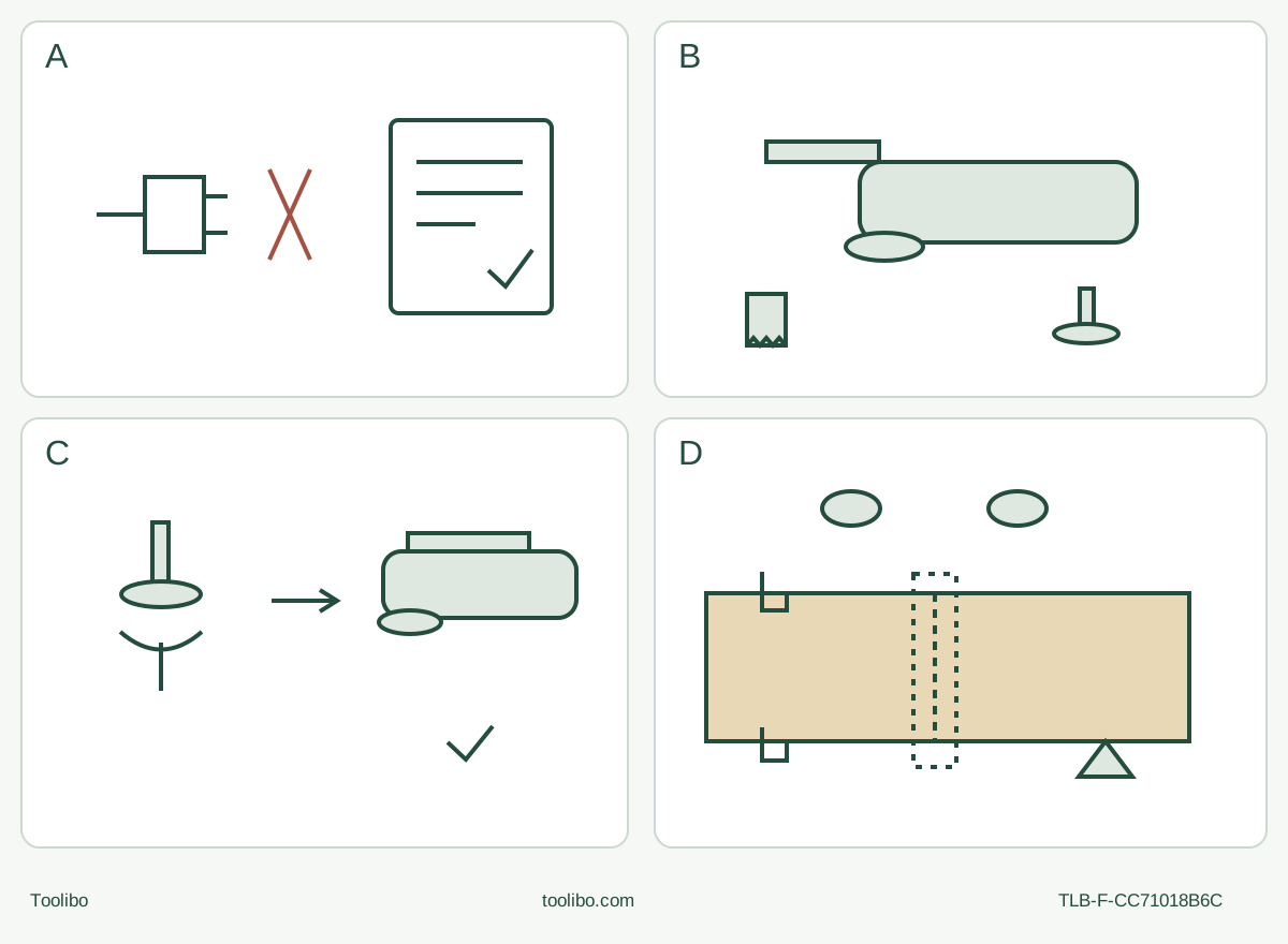
A · Match and isolate
Match the selected body, supply and separately qualified blade; OFF, full stop and unplug before accessory handling.
B · Open and remove
Flip the lever forward, remove the original flange and cooled old accessory. Keep original parts identified; no stacked blades.
C · Hold, close, check
Seat all matching holes and pins, replace and momentarily support the flange, then lever back to its original position. Check no movement while unplugged.
D · Complete and inspect
Use both grips, qualified dust controls and full support/clearance. Reach intended speed before contact, feed lightly, then stop, isolate and accept both faces.
Original schematic, not scale or a complete exploded assembly. Pin count and flange dimensions are not specified. C requires the original flange to be held momentarily before closing the lever; its check is unplugged only. D does not substitute for actual two-hand insulated grips or underside clearance.
Match the selected body before buying a blade
This is an existing-owner project for the US BAUER 19101-B, item 59163, actual UPC 193175457745 and matching 21j instructions. The current product page links several manuals, including a 56509 file and another 59163 UPC. A similar red housing is not evidence that those bodies, parts or instructions are interchangeable. Resolve the actual nameplate and supplied-document match first; this page counts one body, not every package listed together.
The result is one short straight separating cut in a new, dry, untreated and uncoated loose softwood sample, followed by an isolated inspection of both faces. It is not installed trim removal, a hidden-service cut or a performance test. The cover says accessories are sold separately. Here the independently identified original HERCULES HA23-63, item 70251, is the selected blade: its own Harbor Freight product identifies softwood/hardwood, a maximum 20,000 OPM and BAUER compatibility. That evidence does not approve every “universal” blade or a visually similar replacement.
Before proceeding, positively match the actual original blade, its material approval, rating, mount and usable reach. The selected tool manual specifies 11,000–20,000 OPM. The blade must reach through the actual stock while its entire moving envelope remains clear; neither its nominal width nor this article supplies a cutting-depth guarantee. A missing identification, uncertain rating or incomplete original flange assembly means stop for manufacturer clarification, not an energized fit test.
Person, supply and work-area gates
Read the complete matched manual, particularly printed pages 2–6. Do not work tired or impaired. Its vibration precautions exclude pregnant users and people with impaired hand circulation, past hand injury, nervous-system disorders, diabetes or Raynaud’s disease. Regular or extended users should first have a medical examination and then regular checks; vibration symptoms require prompt medical advice. Pacemaker users must consult their physician before use and avoid operating alone. Do not smoke while using the tool; use suitable gloves, breaks and the source precautions rather than treating a small sample as exemption. These are use restrictions, not medical-treatment instructions.
The actual nameplate must match the documented 120 VAC, 60 Hz, 3 A supply. Use the intact original plug and cord with the appropriate outlet; never alter the plug or improvise grounding on this double-insulated tool. If an extension is unavoidable, qualify its actual length, rating, condition and environment against the matched manual rather than choosing it by appearance. Stop for an unreliable switch, damaged cord, loose original hardware, cracked housing, misalignment, binding or any unexplained condition. Internal electrical, cord or brush work belongs to qualified service.
Use a dry, clean, well-lit, non-explosive work area with stable footing and bystanders, children and pets excluded. Inspect both faces and the full cut route for nails, screws, staples and other foreign material. Exclude painted, treated, composite, contaminated or unidentified stock from this project. There must be no nearby service lines or other concealed hazard in the work envelope.
Wear ANSI-approved safety goggles with side shields, appropriate hearing protection, suitable gloves and NIOSH-approved respiratory protection appropriate to the actual dust hazard. Provide ventilation and use required available dust-collection facilities correctly. Before connecting equipment, switch OFF, wait for complete stop and unplug the tool; isolate the extractor under its own instructions. Any chosen extraction system must be correctly connected, operating and checked under those instructions before cutting. No native saw-blade capture hood or numerical extraction threshold is established here. If the actual dust controls cannot be qualified, the cut does not start.
Open, replace, support the flange, then close
With the switch OFF, the mechanism completely stopped and the plug disconnected, let an old accessory cool. Wear protective gloves for sharp accessory handling and keep fingers away from the cutting edge and lever pinch points. Inspect the actual blade for cracks, bending, breakage, dullness or suspected damage; do not reuse a doubtful blade. Keep the original flange assembly intact and identifiable.
Follow printed page 8 in order:
- Flip the release lever forward to the open position and remove the original flange assembly. Remove the old accessory before fitting a replacement; do not stack blades.
- Seat the selected blade on the shaft fitting pins, with all corresponding holes correctly aligned and the blade fully seated. This project uses a straight-ahead blade orientation. The manual’s broader angle allowance is not a reason to rotate a blade during a cut or ignore its clearance.
- Reattach the original flange assembly and hold it in place momentarily to keep the accessory secure. This is a required intermediate action, not proof of final locking.
- Flip the release lever back to its original position to secure the accessory. Do not substitute another model’s flange, thread a guessed fastener or add washers.
- While still unplugged, check that the accessory cannot move on the spindle. If it moves, repeat the documented isolated seating sequence with the holes and pins correctly aligned. Persistent movement, damaged parts or uncertain seating requires qualified correction; never start the motor to see whether it settles.
No torque value or counted pin arrangement is supplied by this article. Remove any loose tools from the work area before later connection. The LED worklight does not prove isolation, correct assembly or full standstill.
Arrange a cut that can actually separate
Mark the required line on the sample and check both faces. Clamp the retained portion securely to a stable support. Independently support the waste so it cannot fall unpredictably, pinch the blade or pull the remaining fibers apart; do not rigidly trap both sides of the kerf. Leave the complete underside, blade sweep and exit path clear of the bench, clamps and supports. The blade must stay clear of hands, the tool body, cord and any qualified dust equipment throughout the cut.
Route the cord with enough free movement and no trip, heat, sharp-edge or cutting hazard. Confirm that two-handed insulated gripping, clear ventilation openings and stable footing remain possible from initial contact to separation. Printed page 8 requires both hands; a one-handed marketing picture is not the operating rule for this project. If the stock is too small to clamp safely or the grips and support cannot coexist, change the fixture or stop—not the hand-clearance requirement.
Start clear, feed lightly and finish under control
The actual control is a slide switch, not a trigger. Set the speed dial while OFF and unplugged for this project. Positions run from 1, slowest, to 6, fastest; the manual does not give a numbered softwood recipe. Use the actual blade instructions and a safely supported matching sample to qualify the intended setting, without inventing a universal speed or treating full speed as permission to force.
After all checks, connect power with the switch OFF. Hold both insulated gripping surfaces, keep the blade clear, slide forward to ON and allow the selected operating speed to be reached before contacting wood. Guide the blade along the straight marked path with light pressure. Do not bend or twist a trapped blade to steer a curve. Feed that causes the mechanism to bog, excessive heat, abnormal noise, vibration, accessory movement or support shift means stop, not more force. Maintain the qualified dust controls and keep hands out of the cutting and underside zones.
For this project, the chosen conservative ending is: after complete separation, slide OFF, wait for complete standstill, then withdraw along a clear path and set the tool down safely. That stop-before-withdrawal choice is not presented as a verbatim OEM instruction. Unplug before touching the accessory or inspecting the result. For a bind or abnormal event, stop and isolate before assessing the stock, blade or fixture; there is no powered wobble, reset-button or fault-cooling test here.
Accept the sample or stop the system
Allow the blade and cut material to cool and avoid sharp edges. With the tool unplugged, inspect both faces: the intended line and size must be obtained, the separation must be complete, and there must be no remaining bridge, uncontrolled tear-out, scorching or evidence that support moved. A cut that passes through but fails the intended fit is not accepted. No numerical finish tolerance is invented; correct the documented material, blade or fixture issue before another sample, or seek qualified service for unexplained behavior.
Wipe accessible external surfaces with a clean cloth and keep ventilation openings clear. Do not open the motor, modify the clamp or attempt cord/brush repair. The parts drawing is identification material, not permission for buyer repair or a guarantee that every part is available. Store the isolated tool safely with the sharp accessory protected and the actual document/UPC identification retained.
Evidence boundary
Operating authority is the selected BAUER 19101-B / item 59163, UPC 193175457745, 21j manual: safety 2–6, specification and controls 7, native change and operation 8, care 9 and parts/repair limits 10–11. The separate original HA23-63 / 70251 product establishes the selected blade’s BAUER, wood and rating claims. Generic belt/drum-sander headings, trigger wording or “if equipped” reset language do not create features on this oscillating body. Other UPC manuals, package contents, warranty outcomes and cross-brand parts interchange are not established.
Models referenced