
Recognize the isolated original system
A identifies the original 184 mm, 5/8-inch blade rated at least 5300 rpm and a detached battery. B separates actual depth indicator and zero bevel with a partial tooth. C places 45° left and 0° right. D shows a connected 32 mm extraction hose clear of the guard.
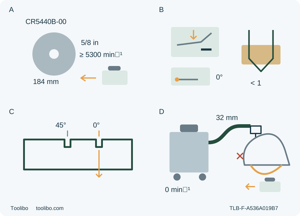
A · Qualify the original system
Match CR5440B-00 and 10/22, original approved blade and commissioned BY519601/QC536001. Remove the battery for checks; current USB-C imagery is not compatibility evidence.
B · Set two independent controls
Battery out: secure actual depth indicator/lever for through-cut with less than a full tooth; separately lock front bevel at zero.
C · Choose the square reference
Use the right 0° notch, not the left 45° notch; establish actual line on equally safe scrap, without a factory-offset assumption.
D · Close the extraction prerequisite
Already installed native port and documented 32 mm hose/extractor must be connected and checked under isolated instructions, then activated before cutting; preserve all guard and hand clearance.
These original conceptual symbols are not to scale and show isolated recognition, not fitting or a running cut. A does not authorize another kit or battery. B requires actual through-cut and less than a full tooth; its separate zero-bevel control is not the depth lever. C is an approximate sightline, not a factory offset. D assumes an already installed native port and qualified active extractor; no universal adapter or airflow claim.
This workflow ends with one supported square crosscut and a recorded decision about the resulting piece. It applies to an existing SKIL CR5440B-00 whose physical identity, controls and supplied 10/22 instructions match. It is not a new-kit commissioning guide, a track tutorial or permission to replace the blade.
The current US page presents a selectable CR5440B-1C USB-C configuration while its included-component text names the older BY519601 battery and QC536001 charger. Do not resolve that inconsistency by assuming that the pictured pack, every carton or every similarly named kit contains the same system. Here the actual BY519601 4 Ah / QC536001 pair must already have been correctly commissioned under its own complete instructions. If that evidence or the physical tool match is missing, hold the task before preparing a cut.
1. Qualify the original cutting system
The matched manual specifies 20 V d.c., 5300 rpm, a 7¼-inch (184 mm) blade and a 5/8-inch (16 mm) arbor. These identify an envelope, not permission to combine independently selected parts. Use only the already correctly installed original approved wood-cutting blade, rated at least 5300 rpm, with correct original washers and bolt. Its direction, thickness, spindle engagement and clean flush washer contact must already be established under the complete instructions. A blade too thick to permit correct outer-washer engagement is forbidden. An uncertain assembly, missing component or need for replacement is a qualified-correction hold—not an invitation to improvise tightening.
Before inspection, release the trigger, wait for complete standstill, depress the release button at the front of the battery and withdraw the pack completely. Keep it away from loose metal that could bridge its terminals. Neither lock-off nor a dark LED is physical isolation. Do not use damaged or modified batteries or admit fluid into the tool, battery or charger.
Check accessible blade condition without touching the teeth: no dull, damaged, bent or missing teeth, pitch buildup or unexplained rubbing. Inspect the foot, handles, housing, adjustment locks, trigger and lock-off for damage, missing or loose parts and reliable movement. A faulty switch, distorted foot, abnormal vibration history or unidentified metal/masonry contamination requires qualified assessment. This task does not include a powered fault test, blade-removal cleaning, sharpening or internal repair. If sharp-blade handling is required under separate complete instructions, the manual requires protective work gloves; handling is not part of this cutting workflow.
2. Check the guard and qualify the workplace
With the battery removed, use the actual lower-guard lift lever to check free movement, immediate full closure and sound spring action. Check that the guard clears the blade and every other part at all angles and all depths of cut, not merely the zero-degree setting selected below. The same clearance obligation matters after a drop. A slow, sticking, damaged or interfering guard means no use until serviced. Never tie or clamp it open. For this ordinary edge-entry cut it operates automatically; the manual’s special plunge retraction is not transferred here.
Choose dry, known clean loose wood that the original blade is approved to cut. Inspect the whole intended path for nails, screws and other foreign material. Reject unknown coatings, hidden services, installed stock or uncertain prior use. No metal, masonry, abrasive wheel, stacked stock or interior opening is covered. A modest sample should be large enough for stable clamping, full base support and a controlled exit; “small scrap” is not automatically a safe specimen.
Use a dry, clean, well-lit workplace without explosive or flammable liquids, gases or dust atmosphere. Keep bystanders away, maintain balanced footing and avoid loose clothing, jewelry or hair near moving parts. Wear ANSI Z87.1 eye protection with side shields, a full face shield when needed, suitable hearing protection and appropriate approved microscopic-particle respiratory protection. Provide ventilation and the qualified extraction described below. PPE does not turn an unsuitable room into an acceptable cutting area.
The manual recommends tool operation at −10 to 40°C and storage at 0 to 40°C. These are not charging-temperature instructions. Use the actual battery and charger instructions for their separate conditions; do not infer them from the tool table or from a kit image.
3. Make dust collection an operating prerequisite
This workflow requires the original native hose port to be already correctly installed and secure. The manual identifies its supplied M4 screw and a 1¼-inch (32 mm) hose connection. That is not universal hose compatibility, an adapter fabrication instruction or a numerical airflow guarantee. Verify the actual tool-side arrangement and extractor/hose documentation for the material and task. If correct native connection or suitable extraction cannot be established, hold the cut.
Make and inspect connections only with the saw OFF, blade stopped and battery removed, and the extractor isolated under its own instructions. Route the hose so it cannot catch the stock, pull the saw sideways, interfere with the lower guard or obstruct either hand throughout entry, travel and exit. Afterwards activate and check the actual extractor according to its instructions before cutting: a connected but inactive hose is not operating dust control. No Bosch pressure or flow threshold is imported into this SKIL system.
4. Plan support, reference and complete separation
Mark a square line from a sound reference edge and identify the retained piece and waste. Place the appearance face down as the manual directs, without promising a damage-free finish on either face. Plan the intended finished dimension and acceptable squareness and surface quality before cutting. This sample proves only whether the actual result meets those stated needs, not a furniture load rating.
Clamp retained stock securely to a stable platform. Support both portions near the cut and their edges without placing supports in the blade path. Broad faces of suitable support timbers provide the source’s stable arrangement; narrow-edge balancing does not. The waste must remain supported yet free to separate without closing the kerf. Do not clamp across the future separation, catch the offcut by hand or expect the blade to support it.
This blade-right body has more foot width to the left of the blade. Retain continuous support beneath that broad area and qualify the complete footprint at the far edge. The manual’s approximate left/right base distances are not a guaranteed guide offset. For this crosscut, use the actual zero-degree sightline and a sound measured square line; do not add a track or optional rip fence. Establish the actual line on equally safe scrap before committing valuable material.
With the pack out, check hand reach, clamp, hose, guard and support clearances beside or safely above the intended travel, blade guarded and teeth clear of the wood. Do not push a projected blade through uncut stock during a rehearsal or force the guard open. If stable full travel and exit cannot be checked without that, change the layout or hold the task. Do not solve a failing setup by removing a clamp during a running cut.
5. Set depth and zero bevel separately
Keep the battery removed. The depth lock lever is beside the main handle. Loosen it, hold the foot flat against the workpiece edge, and raise or lower the saw until the actual indicator mark meets the chosen depth mark. Tighten the lever securely, then check the real projection and clearance. The blade must cut through the stock while less than one full tooth is visible below it and the table and supports remain clear. The later adjustment paragraph allows no more than one tooth, but the stricter safety instruction governs this setup; a scale or illustration cannot override it.
The independent front bevel lock lever releases counterclockwise and locks clockwise. Set the actual indicator to zero and secure the lever. Do not confuse the 45-degree preset stop or track-adjustment knobs with the square-setting lock. Higher angles, stop manipulation and calibration are outside this sample. Recheck both locks and actual depth after setting the angle; if either setting moves or the square relationship is uncertain, obtain qualified correction rather than compensate by steering.
Use the right-hand 0° notch, not the left-hand 45° notch. Both are approximate sightlines. After any change affecting blade, angle or reference contact, a prior offset or sample is no longer sufficient evidence. No factory offset or universal allowable error is claimed.
6. Carry out one ordinary edge-entry cut
Before reconnection, confirm the trigger returns OFF and lock-off functions under the isolated instructions, remove setup tools and check that the hose and clamps remain secure and clear. With the trigger OFF, align the battery’s raised rib with the tool groove and slide the actual qualified pack into place. Its latch must snap and the pack must be secure; do not force a mismatched pack. Do not energize the saw merely to investigate a suspicious switch or guard.
Hold the main handle with one hand and the auxiliary handle with the other, using the insulated gripping surfaces. Keep your body to either side of the blade, not in its line, and keep hands out of the cutting area and from beneath the stock. Neither hand may obstruct automatic guard movement. Support the front of the foot on the retained work with the blade clear before starting.
Press and hold the lock-off with your thumb, then squeeze the trigger with your finger. The lock-off may be released while the trigger remains held. Allow full speed before the blade contacts the wood. Keep the foot flat and feed straight forward with controlled, gentle pressure. Do not force, twist, pulse the trigger or reach for a shifting offcut. The lower guard must open and return automatically as the ordinary cut progresses.
On normal completion, finish the planned separation, release the trigger and maintain control until the blade actually stops. Confirm full guard coverage before lifting or setting the saw down; do not brush it against your leg or clothing. Remove the battery before inspecting the pieces or changing the setup. An advertised brake or the lamp’s delayed extinction is not a stop timer.
Binding or any interruption changes the sequence: immediately release the trigger and hold the saw motionless until complete standstill. Never pull it backwards or withdraw a moving blade. Isolate it before assessing the cause. This guide does not teach restarting an old kerf, repeated thermal resets or continuing a cut after unexplained behaviour.
7. Accept the piece—or record a precise hold
With the pack out, inspect full separation, length from the reference, squareness across the width and edge, and tear-out, scorch or roughness on both faces. Check whether the foot stayed supported, the clamps and settings stayed fixed, waste separated freely and active extraction and hose clearance remained satisfactory. A correctly sized piece does not excuse an unsafe process. Do not handhold a small failed offcut for a corrective recut.
The LED under the auxiliary handle can illuminate on slight trigger movement before the motor runs. Its rapid flashing indicates overload or excessive temperature; slower flashing indicates low battery capacity. Its approximate ten-second post-release illumination does not establish blade motion, isolation or permission to resume. Record an unexpected signal or slowdown and follow the matched complete instructions or qualified service route, not a guessed electrical diagnosis.
Keep accessible vents, switch areas and handles clean without inserting pointed objects or introducing liquids. Remove the pack for cleaning and storage, keep the tool indoors away from children and corrosive agents, and follow the separate power-system storage instructions. Blade removal, solvent cleaning, sharpening and internal work are outside this workflow. A useful handoff records the actual model/manual, battery identity, material, settings, symptom and when it occurred—without reproducing the fault under power.
Models referenced