
Four isolated owner checks
A identifies 5080-01 and original blade rating at least 5300 RPM. B separates depth lever from front wing nut. C selects the right zero reference. D contrasts correct and incorrect wrench storage orientation with disconnected supply.
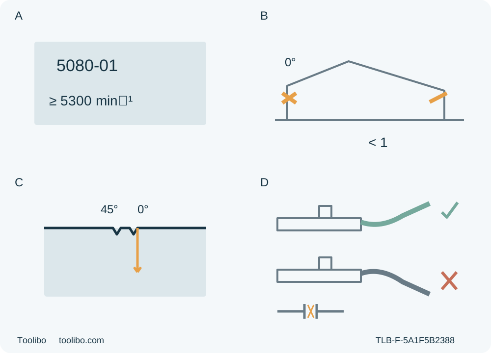
A · Match original round-arbor system
Actual 5080-01 and supplied 04/19 instructions, original 7¼-inch / 5⁄8-inch round wood blade rated at least 5300 RPM, correct existing clutch assembly.
B · Restore the actual sample settings
Unplugged rear lever and front wing nut lock depth and zero separately. After any safe maximum-depth square check, restore strict partial-tooth through-cut; no tab adjustment.
C · Qualify the right-side notch
Use the right reference for a square cut, good face down, and verify actual line/angle on supported scrap. No bevel or guaranteed offset.
D · Store the wrench correctly
Correct orientation and full second-detent engagement keep storage clear of work; remove adjusting tools before startup. Disconnected supply is required for setup.
Original conceptual recognition, not to scale, live cutting or blade fitting. A is the blade-rating prerequisite, not a clutch test. B requires strict partial-tooth through-cut after any safe isolated maximum-depth square check. C is an approximate reference qualified by a real scrap cut, with good face down. D depicts storage orientation only; the wrench must fully engage its second lock detent and setup tools must be removed before start. No port, extraction compatibility, brake time or other model’s light is implied.
The SKIL 5080-01 owner needs a usable answer to a practical question: can this actual corded saw, its original blade system and the available workspace produce one controlled square wood cut? A shared manual or a 51° product headline is not enough. This guide closes a modest edge-entry crosscut and its acceptance, while keeping blade fitting, clutch adjustment and all bevel cutting outside the task.
1. Identify the 5080 body and its qualified original system
Match the physical US 5080-01, its nameplate and supplied instructions to the 04/19 manual that also covers 5180 and 5185. Only the 5080 body is covered here. The current product identifies a 13-amp corded saw; this is not permission to substitute another model based on amperage. In particular, the shared manual’s power-indicator light applies to 5180 and 5185 only. Do not look for that light as a readiness or isolation indicator on the 5080.
The retained original combination wood blade must already be correctly qualified and installed: 7¼ inches, 5⁄8-inch round arbor, rated at least 5300 RPM. The manual describes the supplied combination blade as suitable for crosscuts and rips. That does not approve an arbitrary blade with similar dimensions, a diamond opening or a bore adapter. Confirm the actual original blade’s identity, approval, condition and correct washers/stud before proceeding. If the assembly or prior work is uncertain, stop for qualified correction.
The washers and stud are part of the documented Vari-Torque clutch system. Their existing correct setting matters; overtightening can defeat its function. The clutch is not a blade brake. This article does not teach tightening, loosening, adjustment or a deliberate slip/kickback test. Excessive slipping, a loose or altered assembly, missing original hardware or unknown service history is a hold condition, not a reason to experiment with a wrench.
The product and capacity table mention 51°, while the operating bevel section describes adjustment up to 45°. That difference remains unresolved here. The entire task is at 0° bevel, with no high-angle capacity claim, tab bending or improvised calibration. No plunge, blind cut, masonry, metal, abrasive wheel, wet/treated/coated stock or installed-structure operation is included.
2. Decide whether this workspace is suitable
Select known, clean, dry, bare loose wood suitable for the actual original combination blade. Inspect the complete proposed route and remaining stock for nails, screws and other foreign material. Reject uncertain contamination, concealed objects, unstable stock or a task that demands maximum-capacity handling. Mark a square line, retained side and waste side. Place the good/appearance face down as the manual directs, without assuming that either face will emerge damage-free.
Use the actual nameplate supply, a sound matching plug and cord, and an already qualified electrical arrangement. Do not supply an AC-only tool from DC. If an extension is necessary, its current capacity, total length and condition must satisfy the complete manual and actual nameplate; no rewiring, fuse replacement or extension-selection recipe is given here. Keep the tool and workplace dry, out of rain and away from explosive atmospheres containing flammable liquids, gases or dust. Keep cord routing clear of heat, sharp edges and the whole cutting path.
Wear ANSI Z87.1 eye protection with side shields, and a full face shield when needed, together with appropriate hearing and respiratory protection for the actual task. Provide suitable ventilation and follow material safety information. Keep bystanders and children out, maintain stable nonslip footing and secure hair and loose clothing. Gloves and other loose items must remain clear of moving parts; no hand may be used to collect chips while the tool runs.
The product’s built-in blower clears the sightline; it is not dust extraction. No manufacturer-qualified vacuum port or connection is established by these sources, and this guide does not invent one or tape a hose to the tool. The actual material, workspace and exposure must have adequate documented dust-control arrangements before work begins. If the job requires capture that cannot be safely provided with this system, choose a suitably qualified system or HOLD. Wearing a mask is not a blanket exemption from an unmet dust-control requirement.
3. Inspect with power disconnected
Keep the switch OFF, wait for complete blade standstill and unplug before inspection or adjustment. Check the cord, plug, handles, foot, original blade and accessible mounting condition. Dullness, damage, abnormal binding, misalignment, looseness or unexplained vibration requires correction before use. A known switch fault is not something to diagnose by repeated powered trials. The manual directs immediate unplugging and no further use until repair if the switch fails to start or fails to stop the saw; arrange qualified assistance without exposing yourself to a moving blade.
Check the lower guard and spring for free movement and instant closure before each use. With power isolated, use its lift lever for the prescribed check and verify clearance from the blade and other parts through all documented angles and depths. After a drop, also inspect for damage and the same unobstructed operation. Sluggishness, debris buildup, a bent guard or an ineffective spring means service before use. Never tie or clamp the guard open. Ordinary edge-entry sawing uses its automatic action; no manual hold-open step is part of this cut.
Check that the safety release and trigger operate correctly and that the trigger returns to OFF. Do not defeat the release. Remove any adjusting key or wrench from the working mechanism before starting. If the supplied blade wrench is kept in its on-tool storage position, use the correct orientation shown in Figure 7 and seat it fully to the second lock detent. A wrongly oriented or partly seated wrench can project into the work. This storage check is not blade-service permission.
4. Qualify support and set square-cut geometry
Clamp the retained work securely on a stable platform. Support both portions near the cut and edges as needed so the work cannot sag and pinch the blade. Keep supports outside the blade path and allow the waste to separate independently without being trapped or clamped across the kerf. If timber supports are used, the source shows their broad faces bearing on the work and bench, not an unstable narrow-edge arrangement. Do not cut the table or support structure. Never hold stock or waste in a hand, over a leg or with a helper reaching under the cut.
Keep the broad foot supported on the retained portion throughout entry, feed and exit. Qualify clamp clearance, both-handle reach, body position and cord travel over the entire route. Any isolated reach check must be beside or safely above the intended route, with the blade guarded and no tooth contact—not an attempt to push a stopped blade through stock. If the actual setup cannot maintain control through full separation, do not start. A small offcut is not suitable for a loose-handed corrective cut.
The depth adjustment lever sits between the guard and handle. With the plug out, loosen that lever, hold the foot securely and raise or lower the saw by its handle, then tighten and check the actual depth. Use a through-cut with less than a full tooth exposed below the material. This stricter general safety condition also satisfies the operating section’s no-more-than-one-tooth wording. The lumber scale is a reference, not a substitute for actual stock thickness and clearance below.
The separate front bevel control is a wing nut. The manual’s isolated 90° check begins with the foot at maximum depth, then the wing nut loosened, quadrant set to zero and wing nut retightened before checking blade-to-foot squareness. Only perform that check with a safe, stable unplugged arrangement that keeps the exposed blade clear and hands away from teeth. If it cannot be safely checked, or it is not square, obtain qualified assistance; do not bend the calibration tab. After checking, restore and lock the actual sample depth and reverify the strict partial-tooth through-cut before use. Maximum depth is not the sample setting.
For this square cut, use the right side of the foot’s line-guide notch; the left side is the bevel reference and is not used. The source calls the notch approximate and requires scrap cuts to verify the real line. Keep the intended retained dimension outside the waste kerf and establish the actual relationship on the supported sample. No guaranteed offset or finish tolerance is assumed. The optional rip fence and board-guide installation are not part of this crosscut task.
5. Complete the cut without treating a fault as normal operation
Before connecting power, confirm OFF, closed guard, secure depth lever and bevel wing nut, sound original clutch/blade assembly, safely stored or removed setup tools, clear supports and qualified dust controls. Grip the main handle with one hand and the actual auxiliary handle with the other, using insulated gripping surfaces. Keep both hands away from the blade, out from under the work and away from the area behind the saw. Neither hand may obstruct lower-guard movement. Stand to one side of the blade line, not directly behind it.
Set the front of the foot securely on supported retained stock with the blade clear of the edge. Press the safety release with your thumb from either side of the handle, then pull and hold the trigger. Let the blade reach full speed before contact. Advance with light, continuous pressure, keeping the foot flat and the path straight. Do not force the blade, twist the tool to follow a drifting line or rely on the clutch to make an unsafe feed acceptable.
For a normal cut, maintain the qualified support and finish the cut through the edge before releasing the trigger. Wait for actual complete standstill before withdrawing or lifting the saw. Keep it away from your leg, side and clothing during coast-down; contact can retract the guard. Confirm that the guard covers the blade before secure setdown, then unplug before inspection. Neither the blower nor the clutch provides a stopping-time guarantee.
Binding, interrupted feed, lost support or another abnormal condition overrides the normal finish sequence: release the trigger immediately, hold the saw motionless until the blade stops and isolate power before assessing the cause. Never pull a moving blade backward or lift it out of the kerf. This article does not teach a restart in the old cut, trapped-tool extraction or a powered fault test. If the cause or safe release is unclear, get qualified help and keep the saw out of use.
6. Accept the result and retain the system boundary
After unplugging and cooling, inspect both pieces without contacting sharp edges. Check complete separation, actual line position and size, squareness through the thickness, straightness and face damage. Confirm that neither portion sagged into the kerf, settings did not shift, the guard remained free and cord/dust arrangements stayed controlled. Accept only when the intended result and the complete process are satisfactory; a straight-looking edge alone is not enough.
A sound tool with an ordinary line-reference or zero-setting error may be reconsidered while isolated, then checked on a fresh properly supported sample. Persistent burn, slipping, unusual noise, vibration, binding or loose settings requires qualified assessment. Do not use the troubleshooting table as a reason to adjust the clutch, replace a fuse or fit a different blade within this guide.
Disconnect power for care. Keep accessible vents and controls clean without inserting pointed objects or disassembling the tool. This workflow does not reproduce compressed-air cleaning, kerosene blade cleaning, sharpening, brush service or lubrication procedures. Avoid solvents that damage plastics and refer cord work or internal service to SKIL’s appropriate service personnel. Store the cooled tool dry and out of children’s reach. Record the actual manual, original assembly qualification, supply/dust conditions and sample result; later changes require renewed qualification rather than automatic acceptance.
Models referenced