
PBLCS302 isolated owner checkpoints
Four panels show the original 7-1/4 in assembly, both depth limits, distinct depth and bevel levers with zero setting, and an upper-guard adapter connected to an extractor.
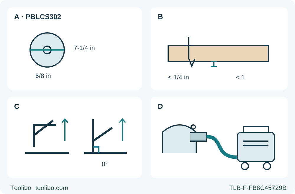
A · Original identity
Require the original qualified recommended 682142005 wood blade and exact native hardware; do not infer replacement equivalence from current retail cards.
B · Two limits together
With the battery removed, verify exposure no greater than 1/4 in and less than a full tooth. The numerical ceiling does not replace the tooth rule.
C · Separate locks
Lift each appropriate lever to release; set depth and zero bevel separately, then push each down to lock. Qualify the zero-notch offset on matching supported scrap.
D · Connected collection
With the battery removed, verify the existing upper-guard adapter and provided screw, then connect the suitable hose and check full-route clearance and dust-control readiness.
All setting panels refer to a removed battery. A identifies the original assembly, not blade fitting. B requires both numerical exposure and tooth limits. C upward arrows indicate release for two separate levers; both must be pushed down to lock. D depicts the existing connected extraction system, not a bare adapter or a universal hose-performance specification.
This workflow takes an already correctly assembled US RYOBI PBLCS302 through a supported square crosscut in clean loose wood, from document and condition checks to an accepted sample. It does not commission a new blade, battery or charger. Match the actual data plate and supplied instructions to manual 999000459, dated 11-20-24 (REV:01), returned by the current official support chain for PBLCS302B.
The B product configuration is not another hardware body. The support record connects that configuration to manual model PBLCS302; it does not promise that every owner received the same kit contents or that this revision applies regardless of the actual tool’s history. Retain any manufacturing suffix when requesting service. If the tool, controls or supplied documents do not match, stop before borrowing settings.
Confirm the original assembly and commissioned power
Require the correctly installed original recommended thin-kerf wood blade and native washers and screw, with known assembly history. The manual’s accessory table identifies blade 682142005. It specifies a 7-1/4 in blade, 5/8 in arbor and 5000 rpm no-load speed; the blade rating must be at least the tool’s maximum marked speed. Thickness must allow the outer washer to engage the spindle flats. Current related blade cards are not evidence that another part number is equivalent.
The full manual includes washer-contact oil and a specific assembly sequence. This article neither disassembles the saw nor substitutes a generic dry-flange rule or partial tightening recipe. Dullness, damage, pitch accumulation, uncertain washers, a missing part or unknown assembly means hold for complete exact instructions and qualified correction. Do not test an unidentified blade just because the diameter seems right.
The tool manual requires batteries and chargers listed in correlation supplement 987000-432. Use only an already commissioned actual system supported by that supplement and the complete instructions for the owner’s exact battery and charger. This article does not qualify a named new pair. A broad ONE+ compatibility statement, current retail recommendation or familiar pack shape is not a substitute for the actual documentary check. Missing instructions or an unresolved pairing blocks this workflow.
Do not use a damaged or modified tool or pack. The manual also prohibits use of a battery or charger that has been dropped or received a sharp blow; absence of a visible crack does not clear that history. Obtain the appropriate manufacturer or authorized-service assessment rather than opening, charging or testing a suspect pack. Protect detached terminals from loose metal under the actual battery instructions.
Isolate and inspect before arranging the sample
Release the trigger, wait for complete standstill and remove the battery by depressing its side latches and withdrawing it fully. Keep the switch locked against accidental starting when handling or carrying. Remove the pack for adjustments, cleaning and nonuse, not merely when changing a blade. Work-light status and a released trigger are not physical isolation.
Wear ANSI Z87.1 eye protection with side shields during inspection and maintenance as well as cutting. With the battery removed, check the lower guard’s free movement and instant closure using its retracting handle. It must not contact the blade or other parts at any angle or depth. Check the spring, and if the saw has been dropped, inspect the lower guard and bumper at all depth settings before any reuse. A defect or uncertain result requires correction before operation; do not tie the guard open or prove a slow guard with a live sample.
Check the handles, base, depth and bevel locks and switch condition. Keep hands out from under the work and away from the blade. The automatic guard cannot protect the exposed underside of a blade already cutting through wood. This sample uses ordinary edge entry, not pocket cutting or manual guard holding.
Select a flat, dry, untreated solid-softwood scrap and matching workpiece of manageable size. Inspect for knots, nails, other foreign material, warping and wetness; do not cut through a knot or nail. The manual permits several wood products, but this initial task does not expand to unknown composition, nonwood blades, abrasive wheels, stacked material or hidden installed work.
Connect the actual dust route and set both depth limits
Use the existing correctly fitted vacuum attachment for this workflow. With the battery removed, verify that it is oriented into the upper-guard dust chute and secured by the provided screw. Connect it to the actual suitable vacuum hose; the manual says the attachment should always be connected when used. A bare attachment is not a collection system. The product describes a 1-1/4 to 1-7/8 in hose range, but physical connection still has to be secure and the extractor suitable for the actual wood dust under its instructions.
Before cutting, operate and check the already-qualified extractor under its own instructions; a connected hose with the extractor switched off does not provide active dust control. Arrange ventilation and suitable dust or face protection for dusty work. Wear hearing protection during extended operation, as the manual requires. Plan hose length and movement through the whole cut, clear of the guard, clamps and feet. Do not release one grip to manage a hose snag. This source supplies no universal installed airflow or vacuum-pressure threshold; do not transfer one from a Bosch model.
With the battery still removed, pull the depth-lock lever upward to release it. Hold the base flat against the work and raise or lower the saw using the upper-guard depth scale and actual bracket/guard indicator relationship, then push the lever down to lock the base. Verify the actual result rather than trusting a remembered lever position.
Two limits apply together: blade exposure below the stock must not exceed 1/4 in, and less than a full tooth must be visible. The numerical ceiling is not permission to expose a whole tooth. Check both on the actual blade and material and confirm full underside clearance from supports. A loose lock or lever that contacts another part before securing the base is a hold; the manual’s E-ring lever repositioning is a separate complete adjustment, not an improvised step here.
For zero bevel, pull the bevel-lock lever up, set the motor housing to zero on its scale and push the lever down to lock securely. The actual square sample must confirm the setting. A failed square result calls for complete exact correction instructions or qualified service, not experimental movement of the factory zero-stop screw. This task does not use 45° or 56°. The current product’s 45° capacity feature conflicts with its specification record and the manual; no combined bevel-capacity promise is made.
Qualify the reference, support and whole travel
Use the 0° blade-guide notch for the square crosscut, not the 45° notch. Blade thickness affects the actual cut, so make a same-material scrap trial along a marked guideline to determine the needed line offset. Mark the wanted side and waste side clearly. If using a straightedge to guide this sample, establish the real base-contact offset with the same assembly and locked settings; do not borrow a P507 measurement.
The base’s width scale is also model-specific: up to 1 in to the right of the blade and 4-1/2 in to the left. It is a reference, not a substitute for securing the work or verifying the finished dimension. The manual recommends the good face down. Inspect the actual trial for splintering instead of promising an undamaged surface.
Clamp the retained work to stable supports near the cut. Independently support the waste and retained portions outside the blade path, with the wider base on the retained supported piece. Waste must remain free to separate without sagging or closing the kerf. Do not hold the stock with the hand that belongs on the front grip or catch a falling piece. Avoid an end-only support layout that allows the panel to bend into the blade.
Check entry, middle and exit for clamp clearance, continuous base support, hose freedom and balanced footing. Assess reach beside or safely above the route while isolated, blade guarded and teeth clear; do not push the projecting teeth through uncut stock as rehearsal. If the far end demands overreaching or a support change during the cut, rearrange first. A visible cut line alone does not make the route ready.
Complete the cut and accept both result and process
After all isolated checks pass, confirm the trigger is released and the lock-off is in its normal protective state. Insert the qualified battery and ensure the latches on both sides snap into place and the pack is secured. Hold the main handle and front pommel/auxiliary grip with both hands, body beside the blade line. Neither hand holds the workpiece. Place the base on supported material with the blade clear of the wood.
Press the lock-off from either side, then depress the trigger. Allow full speed before entering and advance forward with steady even pressure, keeping the base flat and the planned reference stable. The lock-off resets when the trigger is released. Do not force a slowing blade or twist the tool back toward a missed line.
If the blade binds, stalls or the cut is interrupted, release the trigger and hold the saw motionless until the blade completely stops. Never back a moving blade out of the kerf. Remove the battery before investigating. No interrupted-cut restart is taught here. At normal completion, release the trigger, wait for actual complete standstill before lifting, verify lower-guard closure and set the tool down safely; remove the battery before inspection and measurement.
Accept the intended dimension, straightness, square cut and edge finish, but also check the process: both locks remained secure, the guide stayed fixed, support persisted, the hose stayed clear and the waste separated without pinching. A scorched or damaged edge, lost support or abnormal tool behavior is a hold even if the dimension is correct. Record the actual original blade, depth, zero setting, guide relationship and power-document basis before repeating the job.
Treat signals and maintenance as limits, not reset permission
The work light normally illuminates with the trigger and turns off on release. The manual’s diagnostic table distinguishes solid normal illumination, three flashes for low battery, six for excessive force and nine for overtemperature. These are different conditions, not a generic “battery fault.” Record what happened after safely stopping, without repeatedly energizing the saw to reproduce it.
The table also contains waiting and reinsertion actions, including a separate more-than-nine-flashes footnote. This owner sample does not turn those into unconditional reset permission. Consult the complete exact instructions, correct the cause and re-establish every prerequisite; persistent or unexplained behavior needs qualified assistance. No fixed cooldown, LED color or automatic-safe-restart claim is supplied here.
For routine care, remove the pack and use clean cloths for dirt on plastic parts; avoid solvents. Blade chemical cleaning, sharpening, assembly work and internal repair are outside this task. Store securely with the battery removed and keep the full instructions with the tool. Do not use the rafter hook as a body hanger or overhead suspension. An accepted sample qualifies this particular supported wood setup, not a new blade, power pair, recovery procedure or hazardous material.
Models referenced