
Reference, width arithmetic, full-path rehearsal and final blank acceptance
A divides a hypothetical 600 mm width into 300 mm retained, 3 mm kerf and 297 mm waste; B checks a straight reference; C is an isolated guide-path plan; D checks width at three locations and a square end.
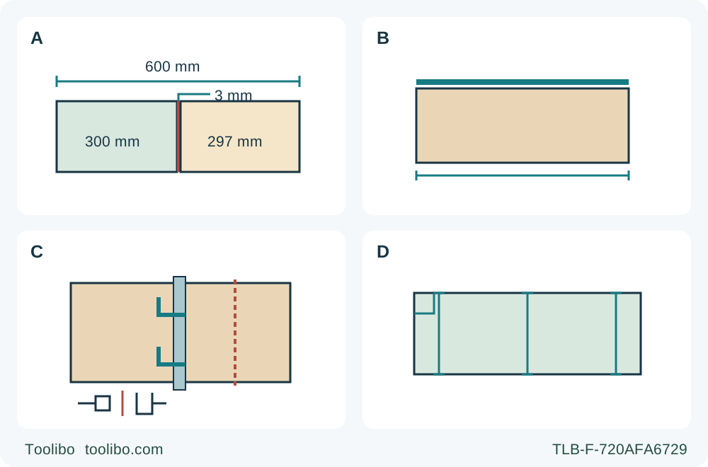
A · Plan retained width and waste
Write the actual dimensions and qualified kerf. In the hypothetical example, 600 − 300 − 3 leaves 297 mm of solid waste; keep the full kerf outside the wanted 300 mm.
B · Qualify the reference edge
Check full-length straightness and panel condition. A bent or damaged edge cannot become a reliable datum merely by following it with a fence.
C · Rehearse the complete isolated path
Unplug and check guide contact, clamps, broad-base support, both-piece behavior, cord, footing and reach from entry through separation. Change an unworkable layout before cutting.
D · Accept width before final length
Measure width near entry, middle and exit and inspect the new edge. Only then rebuild for the final end cut and accept the complete rectangle, faces and edges.
All dimensions in A are an illustrative measured example: 600 − 300 − 3 = 297 mm, not a factory kerf or support limit. B requires an actually straight reference, not blind trust in a panel edge. C is a conceptual unplugged layout check; it does not depict running hand placement or prescribe support spacing, and both pieces still need the complete support plan in the body. D measures entry, middle and exit widths, then requires the final length, square ends and surface condition to pass. This is not shelf installation or a load rating.
A shelf blank is not finished when one cut looks straight. It needs a usable reference edge, consistent width along its length, square ends and an acceptable face and edge condition. This project makes one loose rectangular plywood blank by completing the long rip first, accepting that edge, and only then finishing the length. It does not install a shelf or establish a load rating, span, bracket arrangement or fastening design.
The bounded saw is the US Makita 5007MG matching instructions 884671-946, with its correctly installed original approved wood-cutting assembly. The manufacturer’s exact product page names plywood ripping among its applications. That does not approve every plywood, coating or replacement blade. Confirm the actual panel’s identity and the installed blade’s suitability for that plywood and the required finish before starting. Unknown construction, delamination, embedded fasteners or an uncertain blade makes this a hold, not a trial on the final piece.
The distinct outcome is a parallel-width blank with measurements near the entry, middle and exit of the long cut, an accepted new edge, and a final length and squareness check. The established guide-offset and supported end-cut procedures are prerequisites; this project does not replace them with another guessed base measurement.
Write the blank plan before moving the saw
Identify the intended reference edge, retained face, width, final length and acceptable dimensional and appearance limits. Those limits come from the separate project design, not from the saw’s advertising. If a later installation needs a clearance or thickness allowance, resolve it before cutting; this guide does not supply a universal shelf fit.
For a deliberately hypothetical planning example, start with a sound, manageable panel measured at 1200 mm long and 600 mm wide, with one end already verified square to the chosen straight reference edge. The intended finished blank is 900 mm long and 300 mm wide. If a prior qualified sample established an actual 3 mm kerf for the unchanged assembly, the long-rip waste width would be 600 − 300 − 3 = 297 mm. After that rip, the final length trim would leave 1200 − 900 − 3 = 297 mm of solid end waste.
These are illustrative dimensions and arithmetic, not support spacing, safe overhang limits, a factory kerf or a promise that a particular base fits on 300 mm. Measure your actual material and kerf. If the reference end needs squaring first, measure the remaining length after that operation; do not continue using the example’s original 1200 mm figure.
Mark the retained rectangle and the waste sides clearly. The full kerf goes outside the wanted dimensions. Do not put the center of the blade on a finished-size line and expect the original dimension to remain. Keep enough material for any separately planned finishing allowance, without inventing an allowance after the blank is already undersize.
Qualify the reference instead of copying its defects
Lay a known straight reference against the proposed long edge and inspect its length, not just the corners. A bowed, chipped or damaged edge is a poor datum for parallel width. Check the panel itself for twist, instability and separated layers. Do not force a warped panel flat with excessive clamping and assume it will stay that way after release.
If the chosen edge is not usable, stop this layout and establish an acceptable edge by a separately planned, supported operation, or choose a different blank. Recalculate the available width afterward. A rip fence that follows a crooked edge can reproduce the error; it does not straighten the reference merely because the tool has a fence accessory.
Use a suitable straightedge guide for this project, with the actual saw-to-guide relationship already measured and confirmed on scrap at the same zero bevel and blade configuration. Place it on the retained side so the wider base stays on supported material. Check that this particular base has enough bearing surface along the entire path. Do not infer a safe arrangement solely from the drawing or the example width.
Set the guide from the finished cut line using the verified contact-side offset. Check both ends against the same reference and confirm that clamps have not shifted the guide while tightening. The guide must be long enough to maintain the intended contact through the real entry and exit without an unsupported transition; this is not a universal overhang dimension or permission to borrow a rail-system rule.
Build a continuous long-feed support plan
The manual requires a rip fence or straightedge when ripping and stable work support. For panels it shows support on both sides near the cut and near the edges to reduce sag and pinching. Arrange support for the retained blank and the separating strip, while leaving the complete blade corridor clear. Inspect the underside: a support hidden below the panel is still in the blade’s path if it crosses that corridor.
Consider all three stages: entry, the middle when the separated length is growing, and final separation. The retained piece must keep the base stable throughout. The waste must not drop, twist into the blade or close the kerf. Do not depend on catching it by hand, trapping it between incompatible clamps or putting a helper near the moving blade. If the available supports cannot control both pieces, change the panel size or workspace through a separately qualified plan before this cut.
With the saw unplugged, rehearse the full travel. Check the guide’s clamps, the front grip and rear handle, the cord route, footing and reach. A layout that works for a short crosscut may not allow safe continuous travel over this longer distance. Do not plan to change grip, climb onto the work or reach across the cutting line to finish. If the complete path cannot be controlled, retain the hold rather than improvising halfway through.
Check the panel is secured against shifting without distorting it. A successful support rehearsal includes the pieces after separation, not only the intact panel. The drawing is conceptual; it provides no support load rating and does not authorize cutting into foam or an unverified sacrificial material.
Qualify the surface result on matching scrap
The original installed blade must already be appropriate and sound. This project does not specify a replacement tooth count, teach sharpening or guarantee a chip-free finish. Before committing the planned blank, use a safely supported sample of the same identified plywood and the same settings to check the actual visible face and edge result.
Record which face was oriented where and inspect both faces after stopping and unplugging. Decide whether the result meets the separately chosen appearance requirement. Do not assume that tape, a scored line or a different feed speed automatically cures damage; none of those interventions is taught here. If the approved assembly cannot produce the required result, stop for a properly specified alternative process rather than experimenting on the final piece.
Use the actual owner preparation: eye and hearing protection, appropriate respiratory and dust precautions for the panel, correct nameplate supply and extension cord, a freely moving instantly closing lower guard, with no guard contact against the blade or other parts at all angles and depths of cut, and a trigger that returns OFF. Isolate the saw for depth and zero-bevel settings. The manual allows no more than one tooth beneath the work; this project chooses less than a full tooth and verifies clearance, then secures both adjustments.
Make the rip and accept the new edge
Reconnect only after the checks and rehearsal are complete. Use both the front grip and rear handle, with the body out of the blade line. Start with the base flat and blade clear, wait for full speed, then advance straight and uniformly along the qualified guide without forcing or twisting. Do not pull the saw sideways to correct a developing width error.
If the panel moves, the guide loses contact, the cord catches or the blade binds, release the trigger and hold the tool motionless until the blade stops. Do not pull a moving blade backward. Isolate and reassess the entire arrangement; this project contains no in-kerf restart shortcut. After normal completion, release the trigger, wait for complete standstill and guard coverage, then set down and unplug before inspection.
Measure from the accepted reference edge to the new edge near the entry, middle and exit. Compare all three values with the intended width and the project’s declared tolerance, then check the new edge for straightness and square relationship to the face. A correct middle measurement cannot excuse taper at an end. Inspect face breakout, splits, heat marks and delamination as well as the numbers.
If the edge is bowed, tapered, damaged or already undersize, do not simply run the saw along it again. Decide whether a newly planned smaller blank is acceptable under the separate design, or reject the piece. Do not silently change the finished width to hide a process error.
Finish length only after width acceptance
Use the accepted reference edge and previously verified square end to mark the final length. Rebuild the support and guide arrangement for the end cut; the long-rip setup does not automatically protect a short end offcut. Maintain the wider base on the supported retained blank and keep the waste and exit controlled. Use the complete supported end-cut procedure, with power removed for every setting and layout change.
After final stop and isolation, measure length along both long edges, recheck width at the three locations, and inspect each end with a suitable square against the reference edge. Compare the diagonals as an additional check for an out-of-square rectangle, not as a substitute for straight edges and individual measurements. Inspect both faces and all edges for damage that makes the blank unsuitable for its planned next stage.
Label the accepted dimensions and the reference face and edge. Keep any unresolved defect visible in the record. The completed result is a loose, dimensionally accepted plywood blank ready for a separately designed finishing and installation process—not a tested shelf, not an approved load-bearing assembly, and not evidence that every sheet can be processed with the same support layout.
Models referenced