
A new end becomes zero before the second trim
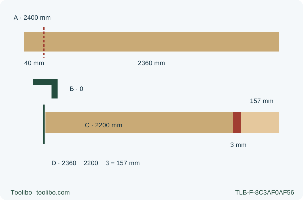
A shows hypothetical 2400 mm stock with a 40 mm first allowance leaving 2360 mm; B identifies the verified end as zero; C marks 2200 mm retained length, 3 mm measured example kerf and 157 mm solid waste; D checks the arithmetic.
A · Plan sound usable stock
In the hypothetical example, 2400 − 40 = 2360 mm remains after the first trim, including that trim’s kerf in the 40 mm allowance. Actual damage and measurements determine your first cut.
B · Verify the first end as zero
After standstill, guard closure and unplugging, check the first end square to the chosen straight reference edge and through the thickness; only then use it as the final-length datum.
C · Rebuild the second supported setup
Turn or reposition the board only with the saw isolated and put aside. Keep the broad base on supported retained wood, recheck guide contact and cord clearance, and place the actual kerf entirely on the waste side.
D · Accept the complete result
The example checks 2360 − 2200 − 3 = 157 mm, not a universal offcut rule. Verify both long-edge lengths and both square ends against the actual project tolerance after the second isolated finish.
Every dimension is an illustrative planning example, not a factory offset, blade width or support limit. The first 40 mm allowance includes its kerf. After verifying the first end, 2360 mm is the assumed usable length; a separately measured 3 mm kerf gives 157 mm second-end solid waste after retaining 2200 mm. The drawing is not to scale and shows reference logic only: supports, clamps and the actual tool position must be planned separately for both cuts, with the saw unplugged for every repositioning.
Trimming both ends of a loose board is not simply repeating the same cut twice. The first cut establishes a trustworthy end; the second must use that new reference while the support, retained side and working position are rebuilt. Measuring from the original rough end, leaving the saw on a falling offcut or rotating the board without rechecking the cable can spoil the result or create a hazardous final separation.
This project uses an already qualified US Makita 5007MG matching manual 884671-946, its actual electrical nameplate and its correctly installed approved wood blade. It is a square, ordinary edge-entry task in known clean wood, not an installation cut, a structural modification, a blade-change lesson or a substitute for the complete owner instructions. The outcome is one board with two verified square ends and a measured final length, plus a record of how both setups stayed supported.
Establish a usable board and a realistic finished length
Start with a loose board that you can move and support without losing control. Inspect its full length for nails, screws, embedded material, decay, severe splits, bow and twist. Reject a piece whose condition or weight makes a stable supported setup impractical. The proposed dimensions below do not certify any span, overhang, support spacing or load rating. Choose actual supports and clamps appropriate to the actual board and equipment; obtain assistance for moving an unwieldy board, not for hand-catching an offcut during cutting.
Identify one sufficiently straight long edge as the reference edge and mark the working face. Both ends will be squared from that same reference edge. If there is no trustworthy straight reference, two carefully drawn lines will not make a reliable rectangular part; prepare the stock by a suitable separate process or choose another board. This project does not straighten its long edges or correct thickness variation.
For an illustrative planning example only, suppose a sound board measures 2400 mm overall. A first end cut will leave 2360 mm of usable board, and the desired finished length is 2200 mm. The first 40 mm allowance includes everything removed at that end, including the saw cut; it is not a promised 40 mm solid offcut. After the first cut, 2360 − 2200 = 160 mm remains for the second kerf and final offcut. If the separately measured kerf were 3 mm, the final solid offcut would be 157 mm. These are hypothetical values, not a factory blade width or a recommendation for how much any damaged end needs removing.
Check that the intended first cut is beyond all damaged material and that enough sound length remains for the second end. If the damage extends farther than expected, redo the length decision before cutting. Do not commit to a target merely because the raw board was sold at a nominal length.
Plan the support twice, before making the first cut
With the saw unplugged, arrange stable support for the full retained length, including support near the cutting area. Support must prevent sagging that closes the kerf, rocking that changes the cut angle and tipping as the ends separate. Every support must stay out of the projected blade path below the board. Do not place a narrow board across two distant supports and assume its centre will remain level under the tool.
Clamp the retained piece to its stable platform without distorting it. The wider part of the 5007MG base belongs on the supported retained board, not the short piece being removed. The offcut must not be trapped so that it presses against the blade, and its eventual movement must not pull the main board out of position. If the trim is too small to support independently, arrange the work so its separation cannot destabilize the retained piece and keep people clear; do not substitute a hand beneath the cut. If that cannot be achieved, change the setup rather than proceed.
Plan the second setup now as well. You may need to turn the board end-for-end, move the supports or change your position to keep the broad base on the retained side again. Do all such repositioning only after the first cut has ended, the blade has stopped, the guard has closed and the saw is unplugged and safely set aside. Never solve an awkward second end by cutting backward, crossing your arms or standing where the blade’s line points toward your body.
Keep the reference-edge and face labels readable after any turn. An end-for-end turn does not authorize transferring a guide offset to a different base contact side. If you change the contact side, blade, angle or guiding arrangement, establish that setup’s real offset again on suitable scrap. The project uses a previously verified guide relationship, not a universal printed distance.
Qualify the tool and rehearse the first path
Before adjustment, physically unplug the saw. Confirm the existing blade and mounting parts are appropriate and undamaged, the lower guard moves freely and closes immediately, with no guard contact against the blade or other parts at all angles and depths of cut, and the trigger returns properly to OFF. A fault or uncertain assembly stops the project. No MGA-only electric brake is assumed on this MG; a light going dark is not proof of isolation, and a stopped blade does not replace a functioning guard.
Set the actual stock depth with the depth-guide lever, using less than a full tooth of projection below the wood for this setup, then secure the lever. Set square bevel and secure its own lever. Do not choose maximum depth simply because the board is long. Inspect underneath with power disconnected to confirm the planned projection clears the supports and bench through the entire cut.
Wear eye and hearing protection and suitable respiratory protection, control dust and keep the area ventilated. Clear the floor and establish firm footing for both the approach and finish. Route the supply cord away from the blade, board corners, clamps and supports so it follows without snagging. Do not create an ad hoc extraction attachment that interferes with the guard or changes the base support.
Mark a square first-end line from the reference edge, label the waste side and place the blade’s cut on that side of the retained boundary. Secure a suitable straightedge at the already measured offset for the selected base contact. A carpenter’s square establishes the line; it is not a hand-held fence to hold beside a running blade. Check the guide’s squareness and clamp clearance, then make an isolated full-path rehearsal without dragging teeth through the stock. The base must remain stable before entry and after exit.
Make the first end, then qualify it as the new datum
At the starting position, keep the blade clear of the wood, connect to the already qualified supply and grip the front grip and rear handle with both hands. Keep your body out of the blade line. Start the saw, wait for full speed and advance forward smoothly along the guide. Do not force the motor, twist to chase a line or reach for a moving offcut. Let the lower guard retract and return automatically during this ordinary edge-start cut.
Complete the cut with the base supported. Release the trigger and hold control until the blade has completely stopped. Confirm guard closure before setting down; unplug before removing clamps, measuring or changing the arrangement. Do not count an imagined braking interval. If the blade binds or the setup shifts, release the trigger, hold motionless until complete stop and unplug before assessing the cause. Do not pull a rotating blade backward to save the line.
Now check the first cut against the marked reference edge using a trustworthy square. Inspect both the across-face squareness and whether the cut is square through the thickness. Check the end for torn fibres or damage that would prevent a reliable measurement. If it is not an acceptable datum, correct the cause with the saw isolated and re-establish a clean end by an appropriate verified setup. Re-measure the usable length afterward. Do not quietly keep the original allowance in the arithmetic when the real end has moved.
Only a verified first end becomes zero for the final length. Mark it clearly as the finished reference end. The old rough end, a convenient clamp edge or a support position is no longer the length datum.
Rebuild the second setup from that finished end
With the saw unplugged and put aside, reposition the board and supports as planned. Re-clamp the retained portion and recheck stability through the second separation. The first arrangement does not remain automatically valid just because the same board is being cut. Re-route the cord from the new starting point, verify all underside clearances and leave room for the saw and guard to clear the far edge.
Measure the required finished length from the newly verified first end along the reference edge. In the hypothetical example, mark 2200 mm from that end, not from the board’s former outer edge. Establish the second square line from the same reference edge and identify which side must remain. Cross-check the measurement before positioning the guide. Measure the other long-edge length as a useful comparison, but do not use an irregular edge to redefine the datum or conceal an out-of-square line.
Place the actual kerf entirely on the second waste side. With the hypothetical 2360 mm usable board and 3 mm measured kerf, the retained part is 2200 mm and the remaining solid offcut is 157 mm: 2200 + 3 + 157 = 2360. If the actual kerf or usable length differs, the offcut changes; the finished boundary should not silently move. Do not centre the blade on the finished line and then subtract another kerf from the target.
Secure the guide using the correct tested contact-side offset. Check depth, bevel lock, guide clamps and lower-guard freedom again. Rehearse the whole route isolated. If the offcut or retained support is less controllable than at the first end, redesign the setup before connecting power. A second cut made from an awkward side is not justified by being the last operation.
Finish the second cut and accept the complete board
Use the same controlled start, two-handed forward feed and supported finish, without treating the first success as permission to skip checks. After complete stop and guard closure, unplug before handling the finished piece or offcut. Keep small waste out of the blade and work area rather than reaching into a coasting tool’s path.
Measure the finished length along both long edges and compare the ends for squareness to the chosen reference and through the thickness. Use the tolerance required by your actual project; this article does not invent a universal cabinet or framing tolerance. Check that neither end is split, burnt or severely torn and that the board was not bowed into a false measurement by the clamps. Release it safely onto support and verify the final condition without loading it as a structure.
Record actual initial usable length, first-end correction, final length, guide contact side and any change made between setups. A short result cannot be repaired by renaming the datum; set it aside for another suitable purpose instead of concealing the error. An oversize or out-of-square result needs a newly planned supported correction, not a casual unsupported sliver cut. Clean the isolated saw and workspace under the exact instructions, inspect the guard again and store safely. The completed project is a board whose two ends and length are verified, with both cut setups accounted for—not merely two separated offcuts.
Models referenced