
Plan the section, then verify the actual edge
A identifies a controlling broad-face width; B shows an ideal 18 mm thick section with an 18 mm horizontal run at 45°; C distinguishes the MG 45° stopper and B cut reference; D checks the resulting section rather than a joint.
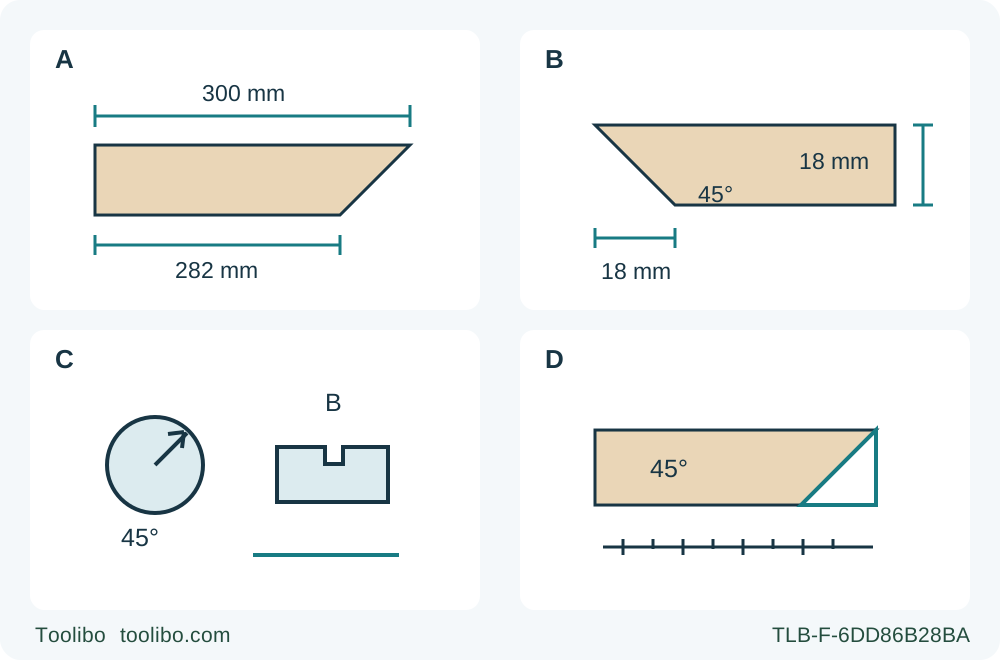
A · Name the controlling face
Identify long and short points and a sound opposite reference edge before marking. Establish actual face orientation on scrap without sacrificing retained-base support.
B · Check the hypothetical geometry
At an ideal 45°, 18 mm thickness gives 18 mm horizontal run. A hypothetical 300 mm long-point width therefore gives 282 mm short-point width; do not treat these as factory dimensions.
C · Set and recalibrate while unplugged
Return provisionally to zero, select the 45° positive stop, tilt and lock, then verify depth and guard clearance. Use MG reference B and a fresh bevel-offset trial, not the square offset.
D · Accept the whole bevel
After trigger release, complete standstill, guard coverage and unplugging, measure the angle and both face widths at entry, middle and exit; reject taper, face damage or loss of control.
All panels are conceptual and not a running saw layout. A names the face whose dimension controls. B is an explicitly hypothetical ideal 18 mm, 45° section: thickness equals horizontal bevel run, but actual thickness and angle must be measured. It does not specify a universal guide offset or kerf allowance. C uses the exact MG stopper and B sighting reference only; perform the full isolated sequence in the body. D means measured edge acceptance, not approval of a 90° assembled corner or a load-bearing joint.
A 45° edge bevel changes more than the saw’s angle. It creates two different face widths, moves the visible cut reference and changes the space needed beneath the panel. This project produces one straight, full-length bevel on a known loose plywood blank, then accepts or rejects its angle, face dimensions and edge condition. It does not build a shelf joint, establish a load rating or promise that two separately cut edges will assemble into an accurate corner.
The tool example is the admitted US Makita 5007MG under manual 884671-946, with an already correctly installed, approved wood blade suitable for the actual plywood. The current manufacturer product description includes plywood cutting. The actual nameplate, supplied instructions and original assembly must match; this is not permission to install a new blade or convert a bore. Use only the documented 45° setting here. Differences between high-angle claims in other product material do not need resolving to perform this bounded task.
Specify the two faces before marking a line
Label the blank’s two broad faces and the intended bevel edge while the saw is unplugged and away from the marking area. Name the face that carries the controlling finished width. Do not write only “300 mm wide” and leave it unclear whether the measurement ends at the bevel’s long point or short point. Identify a sound, straight opposite reference edge from which both face widths can be checked.
Draw the intended end section on paper. At an ideal 45° bevel, the horizontal difference between the long and short points equals the actual panel thickness. For an explicitly hypothetical 18 mm panel, a 300 mm long-point width would imply a 282 mm short-point width: 300 − 18 = 282. These are explanatory dimensions, not a cut list or a guaranteed saw offset. The actual thickness, angle and chosen retained side determine the real result, and the kerf is not a second thickness deduction from that geometric relationship.
Before cutting the blank, establish on comparable scrap which physical face becomes the long-point face with the actual tool and retained-side arrangement. Do not solve a wrong orientation by reaching across the blade, reversing feed or removing the broad base support. If the required face, bevel direction and supported base cannot coexist safely, change the plan rather than trying to rescue it during the cut.
Admit the blank and its support arrangement
Use known, dry, loose plywood without concealed fasteners, unknown coatings, serious delamination or a damaged reference edge. Check the complete original blade approval and material instructions. A label saying “wood” alone does not guarantee an acceptable veneer finish. Define the visible-face and edge-damage limits before the test, and keep the final blank uncut until a representative trial passes.
Choose a blank broad and long enough to remain securely clamped and supported throughout the planned cut. There is no universal safe strip width in this guide. The larger, retained portion must support the wider part of the saw base. Independently support the waste outside the blade path while allowing it to separate without closing the kerf. Do not trap the narrow bevel waste between a clamp, support and the moving blade. Keep hands away from both the underside and the sharp emerging edge.
The tilted blade needs a different below-panel clearance envelope from a square cut. With power physically disconnected, check the full projected tooth path, entry and exit against supports, guide clamps and the bench. Do not simply reuse yesterday’s support spacing. If the work must be carried, balanced or held by a free hand while cutting, this setup has not passed.
Set the MG’s 45° control sequence while unplugged
Switch off, unplug and keep control of the plug before changing depth or bevel. The lamp is powered when plugged in; a light or a released trigger is not isolation. Wear eye protection and appropriate hearing and respiratory protection, manage dust and ventilate the work area. Check the lower guard for free movement, immediate closure and clearance at all angles and depths of cut. A sticking or damaged guard means service, not manual restraint through a normal cut.
Follow the manual’s positive-stop sequence rather than twisting the stop against a tilted base. Loosen the bevel lever, provisionally return the base to 0° and secure the lever. Turn the positive stopper so its arrow points to 45°. Loosen the lever again, tilt to the required 45° position and secure the base firmly. The stop selects the available range; it is not a substitute for locking the lever or checking the actual result.
Set cutting depth with the depth-guide lever and secure it. The manual calls for no more than one tooth below the work; this project chooses the stricter less-than-one-full-tooth setting. Verify actual projection and complete through-cut clearance at the bevel, not just a depth setting retained from a square cut. The source specifies a 45 mm maximum at 45°; that capacity is not permission to bury the blade unnecessarily. If the blade cannot clear the panel while satisfying the documented setup, use another appropriately qualified method.
Recalibrate the guide at this angle
For the 5007MG, the front-base A position is the straight-cut reference and B is the 45° reference. Those letters belong to the saw’s sighting diagram; they are separate from any face labels written on the plywood. Identify B before laying out the sample. Do not follow A and compensate by steering the tool sideways.
Use a rigid, straight auxiliary guide clamped to the retained work, with the base following one consistent contact edge. Calibrate the actual guide-to-kerf relationship at the selected bevel using comparable scrap. The existing square-cut offset is not automatically valid at 45°. Record the face orientation, bevel setting, contact edge and resulting long-point and short-point positions. Measure only after trigger release, complete standstill, guard coverage and unplugging.
Keep the guide fixed through the entire trial. Check that the motor housing, tilted assembly and cord will clear every clamp and that the guide does not obstruct the lower guard. With the saw unplugged, assess the route beside or safely above the intended path, with the blade guarded and no tooth contact; do not drag projected teeth through uncut stock. Plan stable footing and two-hand reach through the far end. If you would need to move a clamp or lean beyond control, rearrange the work first.
Cut the trial, then decide whether to cut the blank
Check that the trigger operates properly and returns to OFF before reconnecting the correct supply. Begin with the base supported and the blade clear of the material. Use the rear handle and front grip with both hands, keeping the body beside rather than in the blade line. Start the saw, wait for full speed and advance gently forward in a straight line, maintaining flat base contact and uniform feed. Do not lift the base to change the bevel or force the blade toward the marked line.
If the blade binds, the work moves or the guide contact is lost, release the trigger and hold the saw motionless until the blade stops. Never withdraw a moving blade or twist it back toward the line. Unplug before investigating; an interrupted or misaligned cut is not resumed by this project. A failed process is not accepted merely because one short part of the edge looks smooth.
At normal completion, release the trigger, retain control until complete standstill and lower-guard coverage, then set down safely and unplug. Check the trial’s actual angle with an appropriate angle reference, not just the saw scale. Measure both broad-face widths from the same qualified reference edge at entry, middle and exit. Check edge straightness, veneer damage and whether the retained face matches the planned long/short-point orientation. These checks establish a repeatable setup; they do not certify a structural joint.
Only if the trial passes should the final blank be marked and supported in the same qualified arrangement. Transfer the accepted guide relationship, not a guessed offset from the nominal 18 mm example. Recheck clamps, depth, bevel lock, guard and the full cord route. Make the final cut with the same controlled entry, forward feed and stopping sequence. There is no running adjustment or hand-held waste catch.
Accept the whole edge, not one attractive corner
Inspect the final blank while the saw remains unplugged. Record actual thickness, selected controlling face, long-point and short-point widths, angle and edge quality. Compare measurements along the full length against the project requirements established before cutting. There is no universal numerical tolerance here: a decorative exposed edge and a later precision joint may demand different acceptance, and neither is established merely by calling the setting 45°.
Reject or hold an edge that tapers unexpectedly, changes angle, tears a required visible face or lacks enough remaining material for the intended dimension. Do not plan a freehand shaving pass along a sharp narrow edge to conceal a failed trial. If another cut is feasible, it needs a newly complete clamped and supported layout with adequate retained material; otherwise choose a different blank or qualified method.
Handle the exposed edge carefully and leave any subsequent edge finishing or assembly to an appropriate complete procedure. With the tool unplugged, clear accessible dust as instructed and return the saw to a known documented setting before storage or the next task. The useful record is the successful face orientation, actual bevel, calibrated guide relationship and complete support plan—not a universal offset or a promise that every 45° edge will fit its partner.
Models referenced