
Stop first; salvage is a measured decision
A shows complete standstill and disconnection; B compares hypothetical widths of 307, 302 and 297 mm with a 300 mm target; C holds a revised specification as a question; D separates a new straight line from a damaged wandering edge.
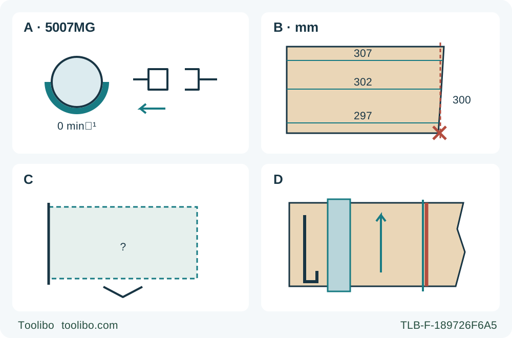
A · Stop and isolate before assessment
Release the trigger and hold the saw motionless until full standstill. Withdraw only in a controlled stopped condition, require guard coverage and unplug; a trapped tool remains a hold.
B · Measure the smallest usable region
Measure from a sound reference edge. Hypothetical stations 307, 302 and 297 mm cannot produce a part requiring 300 mm throughout; averaging does not restore stock.
C · Accept a new specification or reject
A smaller useful blank requires explicit agreement before cutting. Unresolved tool condition, support or material damage prevents proceeding regardless of available width.
D · Build a separate complete layout
Use a qualified straight guide, full retained-base support and independently supported waste free to separate. Begin a normal edge-entry cut only after the cause and all owner prerequisites are resolved.
A is the state after controlled stopped withdrawal and isolation, not permission to withdraw a moving blade. B is an illustrative measurement example: a 297 mm minimum cannot supply the original 300 mm width even if other stations are wider. C requires deliberate acceptance of any new specification; no smaller size is automatically approved. D is a planning diagram, not a running grip or complete support layout. The new line needs the full independently supported retained/waste arrangement in the body, and the original bad kerf stays outside the wanted part.
When a circular saw leaves the intended line, the useful question is not how hard to steer it back. It is whether the tool can be stopped and isolated safely, whether the cause is understood, and whether enough sound material remains for a separately planned cut. This guide completes that decision for an existing US Makita 5007MG under manual 884671-946. It ends with either a qualified new edge-entry cut and accepted result, or a documented tool/workpiece hold.
The scope is a known loose wood workpiece, the correctly installed original approved wood blade, a matching supply and an otherwise qualified owner setup. It does not cover a saw that has been dropped or damaged, an uncontrolled kickback event, an internal plunge, or an unknown blade assembly. Those conditions need their own complete assessment. Nor is this a general instruction to restart in the existing kerf: the selected route is the manual’s stopped withdrawal and realignment on a new line.
Stop before changing direction
The MG operating instructions explicitly prohibit turning or forcing the saw back toward a line that it has failed to follow. Twisting can bind the blade and lead to kickback. Release the trigger and maintain a firm two-hand hold with the saw motionless until the blade comes to a complete stop. Do not pull a moving blade backwards from the kerf or lift the base to drag the teeth sideways.
Only after complete standstill may the tool be withdrawn in a controlled manner under the manual’s instructions. Keep hands away from the blade and underside, allow the lower guard to cover the blade and set the saw down safely. Unplug before investigating the tool, work, guide or supports. The absence of motor noise is not physical isolation, and the MG’s plugged-in lamp is not a safety clearance.
If the stopped tool remains trapped or withdrawal cannot be controlled, do not force it free, loosen supports while it is energized or invent an extraction maneuver. Keep others clear, isolate the supply where safely possible and obtain appropriate assistance. A successful recovery decision can be “leave this setup on hold”; it does not have to end with the same piece being cut today.
Record what moved before rearranging everything
With the tool unplugged and the work stable, mark the intended line, the actual kerf and the retained face. Record where the deviation began and what was observed: a guide that shifted, loss of base contact, a cord snag, a changing stance, a knot or unexpected resistance. These observations are clues, not an electrical or mechanical diagnosis.
Inspect the support arrangement for sagging, movement or a waste piece that closed the kerf. Check whether the wider base had remained on the solidly supported retained portion. Look for guide-clamp contact and whether the cord could pull the saw away from its path. A support that was adequate at entry may have become ineffective as the cut weakened the board. Restore a stable isolated workpiece before measuring it; do not balance a partly separated section by hand.
Do not immediately conclude that the base needs calibration. The manual requires secure depth and bevel locks, suitable sharp blades and properly maintained tools. A changed lock position, damaged component, guard interference or visible blade damage is a reason to stop for complete instructions and qualified correction. This guide does not turn a screw, replace a blade or straighten a base to explain a crooked cut.
Separate a correctable setup problem from a tool hold
Check the unplugged saw’s accessible condition and original assembly without dismantling it. Verify that the lower guard moves freely, closes immediately and does not contact the blade or another part at all angles and depths of cut. A slow or damaged guard, abnormal trigger, damaged cord, questionable blade retention or unresolved cause keeps the tool out of use. Do not run it unloaded to see whether a known defect is “bad enough.”
A clearly identified setup error can sometimes be corrected within the ordinary owner instructions: for example, replacing an inadequate clamping arrangement with a secure one or rerouting the cord out of a snag point. Correcting that observed problem does not prove there are no other faults. Recheck the complete support, guide, grip and clearance plan before classifying the tool and setup as eligible for another cut.
If the event included an actual kickback, impact, repeated binding or unexplained vibration, do not reduce it to a cosmetic line error. Keep a separate record of the event and seek the appropriate complete inspection or service assessment. The conservative hold here is an evidence decision, not a claim that every slight layout mistake requires manufacturer repair.
Decide whether the remaining stock is worth another cut
Measure from a sound, unchanged reference edge, not from the crooked kerf itself. Determine the smallest remaining usable width along the intended finished piece and identify any split, tear-out or partial separation that affects it. The new straight line must leave all required finished material; moving it into the retained side is a loss of stock, not a free correction.
As an explicitly hypothetical decision, if the required finished width is 300 mm but the narrowest sound remaining region can provide only 297 mm, the original 300 mm part cannot be recovered by more sawing. The 3 mm deficit is not repaired by ignoring kerf, measuring from a different face or averaging the widths. Repurpose the piece only if a new, separately accepted specification allows it; otherwise reject it for that part.
When enough stock remains, lay out a new straight line that can be followed from an open edge with the original unwanted kerf outside the wanted finished material. The actual blade path and waste must remain supportable. Do not prescribe a universal minimum distance between old and new cuts: a very narrow, fragmented strip can become trapped in the guard or fail to remain stable. If the proposed route crosses damaged, partly separated or unsupported material, select another layout or stop.
The outcome may be a smaller useful blank, but only if its new dimensions are deliberately accepted before cutting. Do not quietly substitute it into an assembly that depended on the original dimension. This guide makes no load, joint or installation claim for salvaged stock.
Plan a new cut, not an in-kerf rescue
Inspect the proposed new route and remaining stock for nails or other foreign material. Do not proceed unless that route is clear.
Re-establish the ordinary owner prerequisites: matching original assembly and supply, known material, appropriate eye/hearing/respiratory protection, ventilation and dust controls, stable footing and a clear working area. Keep the tool unplugged while setting zero bevel and a conservative less-than-full-tooth depth under the manual’s no-more-than-one-tooth guidance. Secure both depth and bevel adjustments and recheck guard clearance.
Clamp a sound straightedge to the retained work and use the actual calibrated blade-to-contact-edge offset. Do not use the old wandering kerf as a guide. Keep the wider base on supported retained material; independently support the waste outside the blade path and allow it to separate without pinching. Confirm entry, middle and exit clearance, including clamp bodies and the full cord route. A second cut needs a complete setup, not just a fresh pencil mark.
Assess reach beside or safely above the route with the unplugged saw, blade guarded and no tooth contact. Do not push exposed teeth through uncut stock as rehearsal. If the new line moves the guide or saw into an awkward position, rearrange the work. Never plan to change grip, release a work clamp or hold the waste during the running cut.
If the corrected guide relationship or material behavior remains uncertain, qualify it on separate comparable scrap before committing the remaining part. This is a normal supported sample, not a live fault test of a suspect saw. A failed trial returns the setup to hold; repeated attempts do not make the cause established.
Complete the new edge and check both result and process
After the full isolated checks pass, ensure the trigger returns to OFF and reconnect the matching supply. Use the main handle and front grip with both hands, body beside the blade line. Set the base on the supported work with the blade clear, start the saw, wait for full speed and advance gently forward along the new straight guide. Maintain flat base contact and an even feed; do not twist toward the old line or force through renewed resistance.
If the new attempt binds or loses its reference, release the trigger and again hold motionless until complete standstill. Do not continue cutting simply because little material remains. Unplug and reassess; this guide supplies no escalating force, reverse-feed or repeated-reset technique.
At normal completion, release the trigger, wait for full standstill and lower-guard coverage, set down safely and unplug before measuring. Check the final width at several positions, straightness and squareness against the newly accepted specification, and inspect the affected face and edge. Record whether the guide stayed fixed, the retained base stayed supported and the waste separated without pinching.
Accept only if both the finished piece and the process meet the revised plan. Keep the original deviation, identified cause, changed setup and final measurements together in the record. That prevents the next job from repeating the same arrangement and prevents a reduced-size salvage piece from being mistaken for the original part. Where the cause, tool condition or remaining stock is still uncertain, the complete answer is a hold or rejection—not a forced return to the pencil line.
Models referenced